
User's Manual
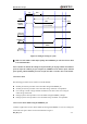
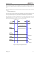

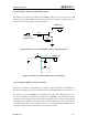

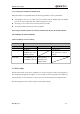
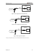
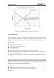
Table Of Contents
- Contents
- Table Index
- Figure Index
- 0. Revision history
- 1. Introduction
- 2. Product concept
- 3. Application interface
- 3.1. Pin
- 3.2. Operating modes
- 3.3. Power supply
- 3.4. Power on and down scenarios
- 3.5. Power saving
- 3.6. Summary of state transitions
- 3.7. RTC backup
- 3.8. Serial interfaces
- 3.9. Audio interfaces
- 3.10. SIM card interface
- 3.12. Behaviors of the RI
- 3.13. Network status indication
- 3.14. Operating status indication
- 4. Antenna interface
- 5. Electrical, reliability and radio characteristics
- 6. Mechanical dimensions
- 7. Storage and Manufacturing
- Appendix A: GPRS coding schemes
- Appendix B: GPRS multi-slot classes

M95 Hardware Design
M95_HD_V1.0 - 40 -
The logic levels are described in the following table.
Table 9: Logic levels of the UART interface
Parameter
Min
Max
Unit
V
IL
0
0.25*VDD_EXT
V
V
IH
0.75*VDD_EXT
VDD_EXT +0.3
V
V
OL
0
0.15*VDD_EXT
V
V
OH
0.85*VDD_EXT
VDD_EXT
V
Table 10: Pin definition of the UART interfaces
Interface
Name
Pin
Function
Debug Port
DBG_RXD
14
Receive data of the debug port
DBG_TXD
15
Transmit data of the debug port
UART Port
DTR
20
Data terminal ready
RXD
21
Receive data of the UART port
TXD
22
Transmit data of the UART port
CTS
23
Clear to send
RTS
24
Request to send
DCD
25
Data carrier detection
RI
26
Ring indicator
3.8.1. UART Port
3.8.1.1 The features of UART Port.
Seven lines on UART interface
Contain data lines TXD and RXD, hardware flow control lines RTS and CTS, other control
lines DTR, DCD and RI
Used for AT command, GPRS data, CSD FAX, etc. Multiplexing function is supported on
the UART Port. So far only the basic mode of multiplexing is available.
Support the communication baud rates as the following:
300,600,1200,2400,4800,9600,14400,19200,28800,38400,57600,115200.
The default setting is autobauding mode. Support the following baud rates for autobauding
function:
4800, 9600, 19200, 38400, 57600, 115200.
The module disables hardware flow control in default, AT command “AT+IFC=2,2” is used to
enable hardware flow control
After setting a fixed baud rate or autobauding, please send “AT” string at that rate. The UART
port is ready when it responds “OK”.