
User's Manual
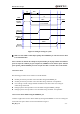
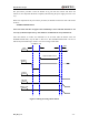

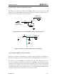

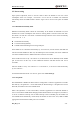
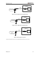
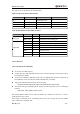
Table Of Contents
- Contents
- Table Index
- Figure Index
- 0. Revision history
- 1. Introduction
- 2. Product concept
- 3. Application interface
- 3.1. Pin
- 3.2. Operating modes
- 3.3. Power supply
- 3.4. Power on and down scenarios
- 3.5. Power saving
- 3.6. Summary of state transitions
- 3.7. RTC backup
- 3.8. Serial interfaces
- 3.9. Audio interfaces
- 3.10. SIM card interface
- 3.12. Behaviors of the RI
- 3.13. Network status indication
- 3.14. Operating status indication
- 4. Antenna interface
- 5. Electrical, reliability and radio characteristics
- 6. Mechanical dimensions
- 7. Storage and Manufacturing
- Appendix A: GPRS coding schemes
- Appendix B: GPRS multi-slot classes

M95 Hardware Design
M95_HD_V1.0 - 37 -
3.5.3. Wake up the module from SLEEP mode
When the module is in the SLEEP mode, the following methods can wake up the module.
If the DTR Pin is set low, it would wake up the module from the SLEEP mode. The UART
port will be active within 20ms after DTR is changed to low level.
Receiving a voice or data call from network wakes up module.
Receiving an SMS from network wakes up module.
Note: DTR pin should be held low level during communication between the module and DTE.
3.6. Summary of state transitions
Table 8: Summary of state transition
Current mode
Next mode
Power down
Normal mode
Sleep mode
Power down
Use PWRKEY
Normal mode
AT+QPOWD, use
PWRKEY pin, or use
EMERG_OFF pin
Use AT command
“AT+QSCLK=1” and pull
DTR up
Sleep mode
Use PWRKEY pin, or
use EMERG_OFF pin
Pull DTR down or
incoming call or
SMS or GPRS
3.7. RTC backup
The RTC (Real Time Clock) can be supplied by an external capacitor or battery (rechargeable or
non-chargeable) through the pin VRTC. A 1.5 K resistor has been integrated in the module for
current limiting. A coin-cell battery or a super-cap can be used to backup power supply for RTC.
The following figures show various sample circuits for RTC backup.