
User's Manual
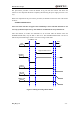


Table Of Contents
- Contents
- Table Index
- Figure Index
- 0. Revision history
- 1. Introduction
- 2. Product concept
- 3. Application interface
- 3.1. Pin
- 3.2. Operating modes
- 3.3. Power supply
- 3.4. Power on and down scenarios
- 3.5. Power saving
- 3.6. Summary of state transitions
- 3.7. RTC backup
- 3.8. Serial interfaces
- 3.9. Audio interfaces
- 3.10. SIM card interface
- 3.12. Behaviors of the RI
- 3.13. Network status indication
- 3.14. Operating status indication
- 4. Antenna interface
- 5. Electrical, reliability and radio characteristics
- 6. Mechanical dimensions
- 7. Storage and Manufacturing
- Appendix A: GPRS coding schemes
- Appendix B: GPRS multi-slot classes

M95 Hardware Design
M95_HD_V1.0 - 36 -
3.5. Power saving
Upon system requirement, there are several actions to drive the module to enter low current
consumption status. For example, “AT+CFUN” can be used to set module into minimum
functionality mode and DTR hardware interface signal can be used to lead system to SLEEP
mode.
3.5.1. Minimum functionality mode
Minimum functionality mode reduces the functionality of the module to minimum level, thus
minimize the current consumption when the slow clocking mode is activated at the same time.
This mode is set with the “AT+CFUN” command which provides the choice of the functionality
levels <fun>=0,1,4.
0: minimum functionality
1: full functionality (default)
4: disable both transmitting and receiving of RF part
If the module is set to minimum functionality by “AT+CFUN=0”, the RF function and SIM card
function would be disabled. In this case, the UART port is still accessible, but all AT commands
correlative with RF function or SIM card function will not be accessible.
If the module has been set by “AT+CFUN=4”, the RF function will be disabled, but the UART
port is still active. In this case, all AT commands correlative with RF function will not be
accessible.
After the module is set by “AT+CFUN=0” or “AT+CFUN=4”, it can return to full functionality
by “AT+CFUN=1”.
For detailed information about “AT+CFUN”, please refer to document [1].
3.5.2. Sleep mode
The SLEEP mode is disabled in default software configuration. Customer’s application can enable
this mode by “AT+QSCLK=1”. On the other hand, the default setting is “AT+QSCLK=0” and in
this mode, the module cannot enter SLEEP mode.
When “AT+QSCLK=1” is sent to the module, customer’s application can control the module to
enter or exit from the SLEEP mode through pin DTR. When DTR is set to high level, and there is
no on-air or hardware interrupt such as GPIO interrupt or data on UART port, the module will
enter SLEEP mode automatically. In this mode, the module can still receive voice, SMS or GPRS
paging from network but the UART port is not accessible.