
User's Manual
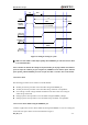
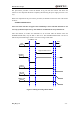


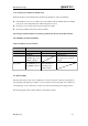
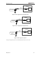
Table Of Contents
- Contents
- Table Index
- Figure Index
- 0. Revision history
- 1. Introduction
- 2. Product concept
- 3. Application interface
- 3.1. Pin
- 3.2. Operating modes
- 3.3. Power supply
- 3.4. Power on and down scenarios
- 3.5. Power saving
- 3.6. Summary of state transitions
- 3.7. RTC backup
- 3.8. Serial interfaces
- 3.9. Audio interfaces
- 3.10. SIM card interface
- 3.12. Behaviors of the RI
- 3.13. Network status indication
- 3.14. Operating status indication
- 4. Antenna interface
- 5. Electrical, reliability and radio characteristics
- 6. Mechanical dimensions
- 7. Storage and Manufacturing
- Appendix A: GPRS coding schemes
- Appendix B: GPRS multi-slot classes

M95 Hardware Design
M95_HD_V1.0 - 35 -
3.4.3. Restart
3.4.3.1. Restart the module using the PWRKEY pin
Customer’s application can restart the module by driving the PWRKEY to a low level voltage for
certain time, which is similar to the way of turning on module. Before restarting the module, at
least 500ms should be delayed after detecting the low level of STATUS. The restart timing is
illustrated as the following figure.
STATUS
(OUTPUT)
H
PWRKEY
(INPUT)
Delay > 0.5s
Turn off
Pull down the PWRKEY
to turn on the module
Restart
Figure 12: Timing of restarting system
The module can also be restarted by the PWRKEY after emergency shutdown.
PWRKEY
(INPUT)
Pulldown > 20ms
Delay>2s
EMERG_OFF
(INPUT)
STATUS
(OUTPUT)
6us
Figure 13: Timing of restarting system after emergency shutdown
3.4.3.2. Restart the module using AT command
Using an AT command “AT+QPOWD=2” can achieve restart of the module. Please refer to
document [1] for the details.