
User's Manual
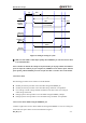


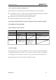
Table Of Contents
- Contents
- Table Index
- Figure Index
- 0. Revision history
- 1. Introduction
- 2. Product concept
- 3. Application interface
- 3.1. Pin
- 3.2. Operating modes
- 3.3. Power supply
- 3.4. Power on and down scenarios
- 3.5. Power saving
- 3.6. Summary of state transitions
- 3.7. RTC backup
- 3.8. Serial interfaces
- 3.9. Audio interfaces
- 3.10. SIM card interface
- 3.12. Behaviors of the RI
- 3.13. Network status indication
- 3.14. Operating status indication
- 4. Antenna interface
- 5. Electrical, reliability and radio characteristics
- 6. Mechanical dimensions
- 7. Storage and Manufacturing
- Appendix A: GPRS coding schemes
- Appendix B: GPRS multi-slot classes

M95 Hardware Design
M95_HD_V1.0 - 32 -
The power-down procedure causes the module to log off from the network and allows the
software to save important data before completely disconnecting the power supply, thus it is a safe
way.
Before the completion of the power-down procedure, the module sends out the result code shown
as below:
NORMAL POWER DOWN
Note: This result code does not appear when autobauding is active and DTE and DCE are not
correctly synchronized after start-up. The module is recommended to set a fixed baud rate.
After that moment, no further AT commands can be executed. Then the module enters the
POWER DOWN mode, only the RTC is still active. The POWER DOWN mode can also be
indicated by the STATUS pin, which is a low level voltage in this mode.
PWRKEY
(INPUT)
STATUS
(OUTPUT)
1s > Pulldown > 0.6s
Logout net about 2s to 12s
VDD_EXT
(OUTPUT)
EMERG_OFF
(OUTPUT)
VBAT
(OUTPUT)
160us
Figure 9: Timing of turning off the module