
User's Manual
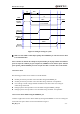
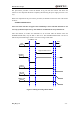


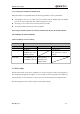
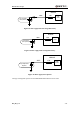
Table Of Contents
- Contents
- Table Index
- Figure Index
- 0. Revision history
- 1. Introduction
- 2. Product concept
- 3. Application interface
- 3.1. Pin
- 3.2. Operating modes
- 3.3. Power supply
- 3.4. Power on and down scenarios
- 3.5. Power saving
- 3.6. Summary of state transitions
- 3.7. RTC backup
- 3.8. Serial interfaces
- 3.9. Audio interfaces
- 3.10. SIM card interface
- 3.12. Behaviors of the RI
- 3.13. Network status indication
- 3.14. Operating status indication
- 4. Antenna interface
- 5. Electrical, reliability and radio characteristics
- 6. Mechanical dimensions
- 7. Storage and Manufacturing
- Appendix A: GPRS coding schemes
- Appendix B: GPRS multi-slot classes

M95 Hardware Design
M95_HD_V1.0 - 31 -
VDD_EXT
(OUTPUT)
V
IL
<0.1*VBAT
VBAT
PWRKEY
(INPUT)
EMERG_OFF
(INPUT)
54ms
250ms
STATUS
(OUTPUT)
800ms
1
>1s
V
IH
> 0.1*VBAT
Figure 8: Timing of turning on system
① Make sure that VBAT is stable before pulling down PWRKEY pin. The time between them
is recommended 30ms.
Note: Customer can monitor the voltage level of the STATUS pin to judge whether the module is
power-on. After the STATUS pin goes to high level, PWRKEY can be released. If the STATUS
pin is ignored, pull the PWRKEY pin to low level for more than 1 second to turn on the module.
3.4.2. Power down
The following procedures can be used to turn off the module:
Normal power down procedure: Turn off module using the PWRKEY pin
Normal power down procedure: Turn off module using command “AT+QPOWD”
Over-voltage or under-voltage automatic shutdown: Take effect when over-voltage or
under-voltage is detected
Emergent power down procedure: Turn off module using the EMERG_OFF pin
Emergent power down procedure: Turn off module using command “AT+QPOWD”
3.4.2.1. Power down module using the PWRKEY pin
Customer’s application can turn off the module by driving the PWRKEY to a low level voltage for
certain time. The power-down scenarios is illustrated in Figure 9.