
User's Manual
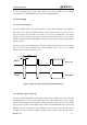
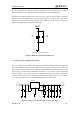
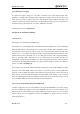
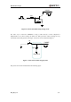
Table Of Contents
- Contents
- Table Index
- Figure Index
- 0. Revision history
- 1. Introduction
- 2. Product concept
- 3. Application interface
- 3.1. Pin
- 3.2. Operating modes
- 3.3. Power supply
- 3.4. Power on and down scenarios
- 3.5. Power saving
- 3.6. Summary of state transitions
- 3.7. RTC backup
- 3.8. Serial interfaces
- 3.9. Audio interfaces
- 3.10. SIM card interface
- 3.12. Behaviors of the RI
- 3.13. Network status indication
- 3.14. Operating status indication
- 4. Antenna interface
- 5. Electrical, reliability and radio characteristics
- 6. Mechanical dimensions
- 7. Storage and Manufacturing
- Appendix A: GPRS coding schemes
- Appendix B: GPRS multi-slot classes

M95 Hardware Design
M95_HD_V1.0 - 30 -
Turn on pulse
PWRKEY
4.7K
47K
Figure 6: Turn on the module using driving circuit
The other way to control the PWRKEY is using a button directly. A TVS component is
indispensable to be placed nearby the button for ESD protection. When pressing the key,
electrostatic strike may generate from finger. A reference circuit is showed in Figure 7.
S1
PWRKEY
TVS1
Close to S1
Figure 7: Turn on the module using keystroke
The power-on scenarios is illustrated as the following figure.