
User's Manual
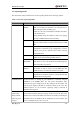
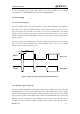
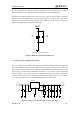
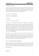
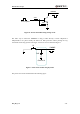
Table Of Contents
- Contents
- Table Index
- Figure Index
- 0. Revision history
- 1. Introduction
- 2. Product concept
- 3. Application interface
- 3.1. Pin
- 3.2. Operating modes
- 3.3. Power supply
- 3.4. Power on and down scenarios
- 3.5. Power saving
- 3.6. Summary of state transitions
- 3.7. RTC backup
- 3.8. Serial interfaces
- 3.9. Audio interfaces
- 3.10. SIM card interface
- 3.12. Behaviors of the RI
- 3.13. Network status indication
- 3.14. Operating status indication
- 4. Antenna interface
- 5. Electrical, reliability and radio characteristics
- 6. Mechanical dimensions
- 7. Storage and Manufacturing
- Appendix A: GPRS coding schemes
- Appendix B: GPRS multi-slot classes

M95 Hardware Design
M95_HD_V1.0 - 29 -
3.3.4. Monitor power supply
To monitor the supply voltage, the “AT+CBC” command can be used which includes three
parameters: charging status, remaining battery capacity and voltage value (in mV). It returns the
0-100 percent of battery capacity and actual value measured between VBAT and GND. The
voltage is automatically measured in period of 5s. The displayed voltage (in mV) is averaged over
the last measuring period before the “AT+CBC” command is executed.
For details, please refer to document [1].
3.4. Power on and down scenarios
3.4.1. Power on
The module can be turned on by PWRKEY pin.
The module is set to autobauding mode (AT+IPR=0) in default configuration. In the autobauding
mode, the URC “RDY” after powering on is not sent to host controller. When the module receives
AT command, it will be powered on after a delay of 2 or 3 seconds. Host controller should firstly
send an “AT” or “at” string in order that the module can detect baud rate of host controller, and it
should send the second or the third “AT” or “at” string until receiving “OK” string from module.
Then an “AT+IPR=x;&W” should be sent to set a fixed baud rate for module and save the
configuration to flash memory of module. After these configurations, the URC “RDY” would be
received from the UART Port of module every time when the module is powered on. Refer to
section “AT+IPR” in document [1].
The hardware flow control is disabled in default configuration. In the simple UART port which
means that only TXD, RXD, GND of the module is connected to host. CTS is pulled down
internally. In this condition, the module can transmit and receive data freely. On the other side, if
RTS, CTS are connected to the host together with TXD, RXD, GND, whether or not to transmit
and receive data depends on the level of RTS and CTS. Then whenever hardware flow is present
or not, the URC “RDY” is sent to host controller in the fixed band rate.
3.4.1.1. Power on the module using the PWRKEY pin
Customer’s application can turn on the module by driving the pin PWRKEY to a low level voltage
and after STATUS pin outputs a high level, PWRKEY pin can be released. Customer may
monitor the level of the STATUS pin to judge whether the module is power-on or not. An open
collector driver circuit is suggested to control the PWRKEY. A simple reference circuit is
illustrated in Figure 6.