
User's Manual
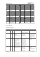
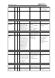
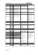
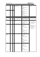
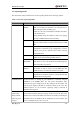
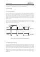
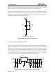
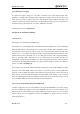
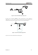
Table Of Contents
- Contents
- Table Index
- Figure Index
- 0. Revision history
- 1. Introduction
- 2. Product concept
- 3. Application interface
- 3.1. Pin
- 3.2. Operating modes
- 3.3. Power supply
- 3.4. Power on and down scenarios
- 3.5. Power saving
- 3.6. Summary of state transitions
- 3.7. RTC backup
- 3.8. Serial interfaces
- 3.9. Audio interfaces
- 3.10. SIM card interface
- 3.12. Behaviors of the RI
- 3.13. Network status indication
- 3.14. Operating status indication
- 4. Antenna interface
- 5. Electrical, reliability and radio characteristics
- 6. Mechanical dimensions
- 7. Storage and Manufacturing
- Appendix A: GPRS coding schemes
- Appendix B: GPRS multi-slot classes

M95 Hardware Design
M95_HD_V1.0 - 22 -
bypass capacitor,
when using this pin
for power supply.
GND
35,
36,
37,
38,
40
Ground
Turn on/off
PIN NAME
PIN
NO.
I/
O
DESCRIPTION
DC
CHARACTERISTICS
COMMENT
PWRKEY
10
I
Power on/off key.
PWRKEY should be
pulled down for a
moment to turn on or
turn off the system.
VILmax=
0.1*VBAT
VIHmin=
0.6*VBAT
VImax=VBAT
Pulled up to VBAT
internally.
Emergency shutdown
PIN NAME
PIN
NO.
I/
O
DESCRIPTION
DC
CHARACTERISTICS
COMMENT
EMERG_
OFF
11
I
Emergency off. Pulled
down for at least
20ms, which will turn
off the module in case
of emergency. Use it
only when normal
shutdown through
PWRKEY or AT
command cannot
perform well.
VILmax=0.4V
VIHmin=2.2V
V
open
max=2.8V
Open drain/collector
driver required in
cellular device
application.
If unused, keep this
pin open.
Module indicator
PIN NAME
PIN
NO.
I/
O
DESCRIPTION
DC
CHARACTERISTICS
COMMENT
STATUS
12
O
Indicate module
operating status. High
level indicates module
is power-on and low
level indicates
power-down.
VOHmin=
0.85*VDD_EXT
VOLmax=
0.15*VDD_EXT
If unused, keep this
pin open.
Audio interface
PIN NAME
PIN
NO.
I/
O
DESCRIPTION
DC
CHARACTERISTICS
COMMENT
MIC1P
MIC1N
4,
5
I
Channel one of
positive and negative
If unused, keep these
pins open.