
User's Manual
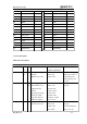
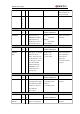
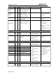
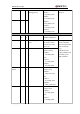
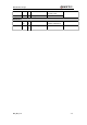
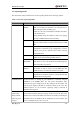
Table Of Contents
- Contents
- Table Index
- Figure Index
- 0. Revision history
- 1. Introduction
- 2. Product concept
- 3. Application interface
- 3.1. Pin
- 3.2. Operating modes
- 3.3. Power supply
- 3.4. Power on and down scenarios
- 3.5. Power saving
- 3.6. Summary of state transitions
- 3.7. RTC backup
- 3.8. Serial interfaces
- 3.9. Audio interfaces
- 3.10. SIM card interface
- 3.12. Behaviors of the RI
- 3.13. Network status indication
- 3.14. Operating status indication
- 4. Antenna interface
- 5. Electrical, reliability and radio characteristics
- 6. Mechanical dimensions
- 7. Storage and Manufacturing
- Appendix A: GPRS coding schemes
- Appendix B: GPRS multi-slot classes

M95 Hardware Design
M95_HD_V1.0 - 21 -
13
NETLIGHT
O
14
DBG_RXD
I
15
DBG_TXD
O
16
RESERVED
17
RESERVED
18
RESERVED
19
VDD_EXT
O
20
DTR
I
21
RXD
I
22
TXD
O
23
CTS
O
24
RTS
I
25
DCD
O
26
RI
O
27
SIM_VDD
O
28
SIM_RST
O
29
SIM_DATA
I/O
30
SIM_CLK
O
31
SIM_GND
32
VRTC
I/O
33
VBAT
I
34
VBAT
I
35
GND
36
GND
37
GND
38
GND
39
RF_ANT
I/O
40
GND
41
RESERVED
42
RESERVED
3.1.2. Pin description
Table 6: Pin description
Power supply
PIN NAME
PIN
NO.
I/
O
DESCRIPTION
DC
CHARACTERISTICS
COMMENT
VBAT
33,
34
I
Main power supply of
module:
VBAT=3.3V~4.6V
Vmax= 4.6V
Vmin=3.3V
Vnorm=4.0V
Make sure that supply
sufficient current in a
transmitting burst
which typically rises
to 1.6A.
VRTC
32
I/
O
Power supply for RTC
when VBAT is not
supplied for the
system.
Charging for backup
battery or golden
capacitor when the
VBAT is supplied.
VImax=VBAT
VImin=2.6V
VInorm=2.8V
VOmax=2.85V
VOmin=2.6V
VOnorm=2.8V
Iout(max)= 730uA
Iin=2.6~5 uA
If unused, keep this
pin open.
VDD_EXT
19
O
Supply 2.8V voltage
for external circuit.
Vmax=2.9V
Vmin=2.7V
Vnorm=2.8V
Imax=20mA
1. If unused, keep this
pin open.
2. Recommended to
add a 2.2~4.7uF