
User's Manual
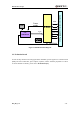
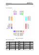
Table Of Contents
- Contents
- Table Index
- Figure Index
- 0. Revision history
- 1. Introduction
- 2. Product concept
- 3. Application interface
- 3.1. Pin
- 3.2. Operating modes
- 3.3. Power supply
- 3.4. Power on and down scenarios
- 3.5. Power saving
- 3.6. Summary of state transitions
- 3.7. RTC backup
- 3.8. Serial interfaces
- 3.9. Audio interfaces
- 3.10. SIM card interface
- 3.12. Behaviors of the RI
- 3.13. Network status indication
- 3.14. Operating status indication
- 4. Antenna interface
- 5. Electrical, reliability and radio characteristics
- 6. Mechanical dimensions
- 7. Storage and Manufacturing
- Appendix A: GPRS coding schemes
- Appendix B: GPRS multi-slot classes

M95 Hardware Design
M95_HD_V1.0 - 18 -
MT6252D
32.768K
Contro
l
26M
Power
supply
UART
SIM
VDD_EXT
AUDIO
PWRKEY
EMERG_OFF
VRTC
RF_ANTENNA
PA
TQM6M4068
Application Interface (42-SMD Pads)
Figure 1: Module functional diagram
2.3. Evaluation board
In order to help customer to develop applications with M95, Quectel supplies an evaluation board
(EVB), RS-232 to USB cable, power adapter, earphone, antenna and other peripherals to control
or test the module. For details, please refer to the document [12].