
User's Manual

Quectel
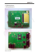
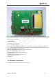
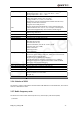
Figure 2: EVB bottom view
A: Debug port
B: Main UART port
C: Test points
D: Adapter interface
E: Module operating status indication LEDs
F: PWRKEY button
G: EMERG_OFF button
H: VBAT switch
I: VCHG switch (charge function)
J: Download switch
K: Connector for M10-TE-A board
L: Screw holes for fixing the M10-TE-A
M: Headset socket
N: Handset socket of audio channel 2
O: Handset socket of audio channel 1
P: Antenna connector fixing hole
Q: Screw holes for EVB placement
R: SIM card socket
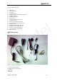
1.2 EVB accessory
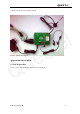
Figure 3: Accessory introduction
A: 5V DC switching adapter
B: USB to UART converter cable
C: Antenna
D: RF cable
E: Headset
M10_User_Guide_V1.00 - 4 -