GV57(N) User Manual GV57(N) User Manual GSM/GPRS/GNSS Tracker TRACGV57UM001 Version: 1.
GV57(N) User Manual Document Title GV57 User Manual Version 1.01 Date 2022-07-06 Status Release Document Control ID TRACGV57UM001 General Notes Queclink offers this information as a service to its customers, to support application and engineering efforts that use the products designed by Queclink. The information provided is based upon requirements specifically provided to Queclink by the customers.
GV57(N) User Manual Contents Contents ............................................................................................................................................ 2 Table Index ........................................................................................................................................ 3 Figure Index....................................................................................................................................... 4 0. Revision History .........
GV57(N) User Manual Table Index TABLE 1. GV57(N) PARTS LIST .................................................................................................................... 7 TABLE 2: ELECTRICAL CHARACTERISTICS OF IGNITION DETECTION ........................................................ 12 TABLE 3: ELECTRICAL CHARACTERISTICS OF DIGITAL INPUT................................................................... 12 TABLE 4: ELECTRICAL CHARACTERISTICS OF DIGITAL OUTPUT .....................................
GV57(N) User Manual Figure Index Figure 1. Appearance of GV57(N) ..................................................................................................... 7 Figure 2. GV57(N) 5-Pin Cable ........................................................................................................... 8 Figure 3. GV57(N) Micro USB Connector .......................................................................................... 8 Figure 4. Opening the Case ............................................
GV57(N) User Manual 0. Revision History Version Date Author Description of Change 1.00 2020-05-20 Stefan Chang Initial 1.01 2022-07-06 Daniel Cheng Added GV57N related information.
GV57(N) User Manual 1. Introduction GV57(N) is a mini GNSS tracker designed for a wide variety of vehicle tracking applications. Its built-in GNSS receiver has superior sensitivity and fast time to first fix. Its dual band GPRS/GSM subsystem supports 850/1900 MHz, allowing the GV57(N)'s location to be monitored in real time or periodically tracked by a backend server and mobile devices.
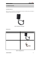
GV57(N) User Manual 2. Product Overview 2.1 Check Parts List Before starting, check whether all the following items have been included with your GV57(N). If anything is missing, please contact your supplier. Figure 1. Appearance of GV57(N) 2.2 Parts List Name Picture GV57(N) Locator User Cable Table 1.
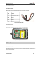
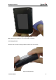
GV57(N) User Manual 2.3 Interface Definition 2.3.1 External Interface GV57(N) has a 5-Pin cable. The pin definition of the 5-Pin cable is shown below. Figure 2. GV57(N) 5-Pin Cable 2.3.2 Internal Interface GV57(N) has a micro USB connector which is shown in the following figure. Figure 3. GV57(N) Micro USB Connector 3. Getting Started 3.1 Opening the Case Insert the triangular-pry-opener into the gap of the case as shown below, and push the opener up until the case is unsnapped.
GV57(N) User Manual Figure 4. Opening the Case Note: Waterproof equipment. Don’t disassemble repeatedly. 3.2 Closing the Case Place the cover as shown in the figure below. Slide the cover until it snaps. Figure 5.
GV57(N) User Manual 3.3 Installing a SIM Card Open the case and ensure the device is not powered (unplug the 5-Pin cable and switch the internal battery to OFF position). Slide the holder to open the SIM card holder. Insert the SIM card into the holder as shown below with the gold-colored contact area facing down. Take care to align the cut mark. Close the SIM card holder. Close the case. Figure 6. Installing a SIM Card 3.4 Installing the Internal Backup Battery Figure 7.
GV57(N) User Manual 3.5 Switching on the Backup Battery To use the backup battery, the switch must be in the ON position. Switch and ON/OFF position are shown below. Figure 8. Switch and ON/OFF Position Note: 1. The switch must be in the “OFF” position when shipped on an aircraft. 2. When the switch is in the “OFF” position, the battery cannot be charged or discharged. 3. To reset the device: Remove the external DC power and then switch off the backup battery.
GV57(N) User Manual 3.7 Ignition Detection Table 2: Electrical Characteristics of Ignition Detection Logical Status Electrical Characteristics Active 5.0V to 32V Inactive 0V to 3V or open IGN (White) is used for ignition detection. An alternative to connecting to the ignition switch is to find a non-permanent power source that is only available when the vehicle is running, for example, the power source for the FM radio.
GV57(N) User Manual 1 Enable <1.5V @ 150mA 2 Disable Open drain Table 4: Electrical Characteristics of Digital Output 3.10 LED Status GV57(N) has two status LEDs that are CELL LED and GNSS LED. Figure 11. GV57(N) LEDs on the Case LED Device Status LED Status CELL (Red) Device is searching GSM network. Fast flashing Device has been registered to GSM network. Slow flashing SIM card needs pin code to unlock. On GNSS chip is powered off. Off GNSS sends no data or data format error occurs.
GV57(N) User Manual 3.11 Motion Sensor Direction GV57(N) has an internal 3-axis accelerometer supporting driving behavior monitoring and motion detection. The following shows the directions of the motion sensor. The Z axis faces straight down. Figure 12. Motion Sensor Direction Note : This equipment has been tested and found to comply with the limits for a Class B digital device, pursuant to part 15 of the FCC Rules.