GV55VC User manual CDMA2000-1X/GPS Tracker User Manual GV55VC TRACGV55VCUM001 Revision: 1.00 http://www.queclink.com sales@queclink.
GV55VC User manual Document Title GV55VC User Manual Version 1.00 Date 2014-10-30 Status Release Document Control ID TRACGV55VCUM001 General Notes Queclink offers this information as a service to its customers, to support application and engineering efforts that use the products designed by Queclink. The information provided is based upon requirements specifically provided to Queclink by the customers.
GV55VC User manual NOTE: This equipment has been tested and found to comply with the limits for a Class B digital device, pursuant to part 15 of the FCC Rules. These limits are designed to provide reasonable protection against harmful interference in a residential installation. This equipment generates, uses and can radiate radio frequency energy and, if not installed and used in accordance with the instructions, may cause harmful interference to radio communications.
GV55VC User manual Table Index TABLE 1. GV55VC PROTOCOL REFERENCE............................................................................7 TABLE 2. TERMS AND ABBREVIATIONS..................................................................................7 TABLE 3. PART LIST......................................................................................................................9 TABLE 4. DESCRIPTION OF 6 PIN CONNECTIONS................................................................
GV55VC User manual Figure Index FIGURE 1. FIGURE 2. APPEARANCE OF GV55VC.........................................................................................8 THE 6 PIN CONNECTOR ON THE GV55VC..............................................................9 FIGURE 3. OPENING THE CASE..................................................................................................11 FIGURE 4. CLOSING THE CASE.............................................................................................
GV55VC User manual Revision History Revision Date Author Description of change 1.
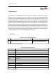
GV55VC User manual 1 Introduction The GV55VC is a powerful GPS locator designed for vehicle or asset tracking. It has superior receiver sensitivity, fast TTFF (Time to First Fix) and supports Dual-Band CDMA2000-1x frequencies 800/1900, its location can be monitored in real time or be periodically tracked by a backend server or other specified terminals. The GV55VC has multiple input/output interfaces that can be used for monitoring or controlling external devices.
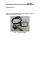
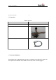
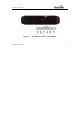
GV55VC User manual 2 Product Overview 2.1. Check Part List Before starting, check all the following items have been included with your GV55VC. If anything is missing, please contact your supplier. Figure 1.
GV55VC User manual TRACGV55VCUM001 -8- 2.2. Parts List Table 3. Part List Name GV55VC Locator Picture 74mm*50mm*13.5mm User Cable DATA_CABLE_M (Optional) 2.3. Interface Definition The GV55VC has a 6 PIN interface connector. It contains the connections for power, I/O.
GV55VC User manual Figure 2.
GV55VC User manual Table 4. Description of 6 PIN Connections Index Description Comment 1 VIN External DC power input, 8-32V 2 GND GND 3 IGN Ignition input, positive trigger 4 IN1 Digital input, negative trigger 5 OUT2 Open drain, 150mA max 6 OUT1 Open drain, 150mA max ,with latch circuit 2.4. GV55VC User Cable Colour Table 5.
GV55VC User manual 3 .Getting Started 3.1. Opening the Case Figure 3. Opening the Case Insert the triangular-pry-opener into the gap of the case as shown below, push the opener up until the case unsnapped. 3.2. Closing the Case Figure 4. Closing the Case Place the cover on the bottom in the position as shown in the following figure. Slide the cover against the direction of the arrow until it snapped.
GV55VC User manual 3.3. Power Connection VIN (PIN1) / GND (PIN2) are the power input pins. The input voltage range for this device is from 8V to 32V. The device is designed to be installed in vehicles that operate on 12V/24V vehicle without the need for external transformers. Figure 5. Typical Power Connection 3.4. Ignition Detection Table 6. Electrical Characteristics of Ignition Detection Logical State Electrical State Active 5.0V to 32V Inactive 0V to 3V or Open Figure 6.
GV55VC User manual FM radio. IGN signal can be configured to start transmitting information to backend server when ignition is on; and enter power saving mode when ignition is off. 3.5. Digital Inputs There are one general purpose digital inputs on GV55VC. They are all negative trigger. Table 7. Electrical Characteristics of the digital inputs Logical State Electrical Characteristics Active 0V to 0.8V Inactive Open The following diagram shows the recommended connection of a digital input. Figure 7.
GV55VC User manual Figure 8. Digital Output Internal Drive Circuit Table 8. Electrical Characteristics of Digital Outputs Logical State Electrical Characteristics Enable <1.
GV55VC User manual Figure 9. Typical Connection with Relay Figure 10. Typical Connection with LED Note: 1 - OUT1 will latch the output state during reset. 2- Many modern relays come with a flyback diode pre-installed internal to the relay itself. If the relay has this diode, insure the proper relay polarity connected is used. If this diode is not internal, it should be added externally. A common diode such as a 1N4004 will work in most circumstances. 3.7. Device Status LED Figure 11.
GV55VC User manual Table 9. Definition of Device status and LED CELL (note1) GPS (note 2) PWR (note 2) Device is searching CELL network Fast flashing Device has registered to CELL network. Slow flashing GPS chip is powered off OFF GPS sends no data or data format error Slow flashing GPS chip is searching GPS info. Fast flashing GPS chip has gotten GPS info.
GV55VC User manual Figure 12.