GV55 User manual GSM/GPRS/GPS Tracker User Manual TRACGV55NUM001 Version:[1.
GV55N User manual Document Title GV55N User Manual Version 1.00 Date 2015-03-18 Status Release Document Control ID TRACGV55NUM001 General Notes Queclink offers this information as a service to its customers, to support application and engineering efforts that use the products designed by Queclink. The information provided is based upon requirements specifically provided to Queclink by the customers.
GV55N User manual - Increase the separation between the equipment and receiver. -Connect the equipment into an outlet on a circuit different from that to which the receiver is connected. -Consult the dealer or an experienced radio/TV technician for help. Copyright This document contains proprietary technical information which is the property of Queclink Limited.
GV55N User manual Table Index Table 1. GV55N Protocol Reference .................................................................................. 7 Table 2. Terms and Abbreviations ...................................................................................... 7 Table 3. Part List ................................................................................................................ 9 Table 4. Description of 6 PIN Connections ...............................................................
GV55N User manual Figure Index Figure 1. Appearance of GV55N ....................................................................................... 8 Figure 2. The 6 PIN connector on the GV55N .................................................................. 9 Figure 3. Opening the Case ............................................................................................ 11 Figure 4. Closing the Case ..............................................................................................
GV55N User manual Revision History Revision Date Author Description of change 1.
GV55N User manual 1 Introduction The GV55N is a powerful GPS locator designed for vehicle or asset tracking. It has superior receiver sensitivity, fast TTFF (Time to First Fix) and supports Dual-Band GSM frequencies 850/900/1800/1900, its location can be monitored in real time or be periodically tracked by a backend server or other specified terminals. The GV55N has multiple input/output interfaces that can be used for monitoring or controlling external devices.
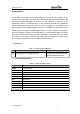
GV55N User manual 2 Product Overview 2.1. Check Part List Before starting, check all the following items have been included with your GV55N. If anything is missing, please contact your supplier. Figure 1.
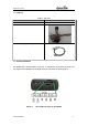
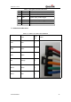
GV55N User manual 2.2. Parts List Table 3. Part List Name Picture GV55N Locator 63mm*50mm*21.8mm User Cable DATA_CABLE_M (Optional) 2.3. Interface Definition The GV55N has a 6 PIN interface connector. It contains the connections for power, I/O. The sequence and definition of the 6PIN connector are shown in following figure: Figure 2.
GV55N User manual Table 4. Description of 6 PIN Connections Index Description Comment 1 VIN External DC power input, 8-32V 2 GND GND 3 IGN Ignition input, positive trigger 4 IN1 Digital input, negative trigger 5 OUT2 Open drain, 150mA max 6 OUT1 Open drain, 150mA max ,with latch circuit 2.4. GV55N User Cable Colour Table 5.
GV55N User manual 3 .Getting Started 3.1. Opening the Case Figure 3. Opening the Case Insert the triangular-pry-opener into the gap of the case as shown below, push the opener up until the case unsnapped. 3.2. Closing the Case Figure 4.
GV55N User manual Place the cover on the bottom in the position as shown in the following figure. Slide the cover against the direction of the arrow until it snapped. 3.3. Installing a SIM Card Open the case and ensure the unit is not powered (unplug the 6Pin cable and switch the internal battery to off position). Slide the holder right to open the SIM card. Insert the SIM card into the holder as shown below with the gold-colored contact area facing down taking care to align the cut mark.
GV55N User manual 3.5. Switch ON the Backup Battery To use the GV55N backup battery, the switch must be at the ON position. Switch on the case and ON/OFF position are shown below. Figure 7. Switch and ON/OFF position Note: 1-The switch must be on the “OFF” position when shipped on an aircraft. 2-When the switch is on the “OFF” position; the battery cannot be charged or discharged. 3-To reset the device: Remove the external DC power and second switch off the backup battery.
GV55N User manual Figure 8. Typical Power Connection 3.7. Ignition Detection Table 6. Electrical Characteristics of Ignition Detection Logical State Electrical State Active 5.0V to 32V Inactive 0V to 3V or Open Figure 9. Typical Ignition Detection IGN (Pin3)is used for ignition detection. It is strongly recommended to connect this pin to ignition key “RUN” position as shown up.
GV55N User manual IGN signal can be configured to start transmitting information to backend server when ignition is on; and enter power saving mode when ignition is off. 3.8. Digital Inputs There are one general purpose digital inputs on GV55N. They are all negative trigger. Table 7. Electrical Characteristics of the digital inputs Logical State Electrical Characteristics Active 0V to 0.8V Inactive Open The following diagram shows the recommended connection of a digital input. Figure 10.
GV55N User manual Figure 11. Digital Output Internal Drive Circuit Table 8. Electrical Characteristics of Digital Outputs Logical State Electrical Characteristics Enable <1.5V @150mA Disable Open drain Figure 12.
GV55N User manual Figure 13. Typical Connection with LED Note: 1 - OUT1 will latch the output state during reset. 2‐ Many modern relays come with a flyback diode pre-installed internal to the relay itself. If the relay has this diode, insure the proper relay polarity connected is used. If this diode is not internal, it should be added externally. A common diode such as a 1N4004 will work in most circumstances. 3.10.
GV55N User manual LED Device status LED status Figure 14. GV55N LED on the Case GV55N has three status led that GSM GPS PWR led. Table 9.
GV55N User manual GSM (note1) GPS (note 2) PWR (note 2) Device is searching GSM network Fast flashing (Note3) Device has registered to GSM network. Slow flashing (Note4) SIM card needs pin code to unlock. ON GPS chip is powered off OFF GPS sends no data or data format error. Slow flashing GPS chip is searching GPS info. Fast flashing GPS chip has gotten GPS info. ON No external power and internal battery voltage is lower than 3.35V.
GV55N User manual Figure 15.