GV50VC User Manual GV50VC User Manual CDMA2000-1X/GPS Tracker TRACGV50VCUM001 Version: 1.
GV50VC User Manual Document Title GV50VC User Manual Version 1.01 Date 2016-03-18 Status Release Document Control ID TRACGV50VCUM001 General Notes Queclink offers this information as a service to its customers, to support application and engineering efforts that use the products designed by Queclink. The information provided is based upon requirements specifically provided to Queclink by the customers.
GV50VC User Manual Contents Contents ............................................................................................................................................ 2 Table Index ........................................................................................................................................ 3 Figure Index ....................................................................................................................................... 4 0. Revision history .........
GV50VC User Manual Table Index TABLE 1: GV50VC PROTOCOL REFERENCE ................................................................................................ 6 TABLE 2: TERMS AND ABBREVIATIONS .................................................................................................... 6 TABLE 3: DESCRIPTION OF 7PIN CONNECTIONS ....................................................................................... 8 TABLE 4: LED DESCRIPTION ......................................................
GV50VC User Manual Figure Index FIGURE 1: GV50VC APPEARANCE ............................................................................................................. 7 FIGURE 2: THE 7 PIN CONNECTOR ON THE GV50VC ................................................................................ 7 FIGURE 3: TYPICAL POWER CONNECTION ................................................................................................ 9 FIGURE 4: TYPICAL IGNITION DETECTION..........................................
GV50VC User Manual 0. Revision history Revision Date Author Description of change 1.
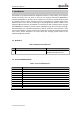
GV50VC User Manual 1. Introduction The GV50VC is a powerful GPS locator designed for vehicle or asset tracking. It has superior receiver sensitivity, fast TTFF (Time to First Fix) and supports Dual-Band CDMA2000-1x frequencies 800/1900, its location can be monitored in real time or be periodically tracked by a backend server or other specified terminals. The GV50VC has multiple input/output interfaces that can be used for monitoring or controlling external devices.
GV50VC User Manual 2. Product Overview 2.1. Appearance Figure 1: GV50VC Appearance 2.2. Interface Definition The GV50VC has a 7 PIN interface connector. It contains the connections for power, I/O.
GV50VC User Manual Table 3: Description of 7PIN Connections Index Description Comment 1 2 3 4 5 6 7 RXD TXD VIN IGN OUT1/IN1 OUT2 GND UART RXD ; TTL UART TXD ; TTL External DC power input,8-16V Ignition input, positive trigger Digital Output/ Input Open drain,150mA max GND 2.3. LED Description GV50VC has two status LED which contain CELL LED and GPS LED. CELL (note1) GPS (note 2) Device is searching CELL network Devicehas registered to CELL network.
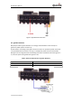
GV50VC User Manual Figure 3: Typical Power Connection 2.5. Ignition Detection IGN (Pin4) is used for ignition detection. It is strongly recommended to connect this pin to ignition key “RUN” position as shown up. An alternative to connecting to the ignition switch is to find a non-permanent power source that is only available when the vehicle is running. For example the power source for the FM radio.
GV50VC User Manual Figure 4: Typical Ignition Detection 2.6. Digital Output/ Input connection OUT1/IN1(PIN5) is a digital Output/Input connection on GV50VC.Ti is of open drain type and the maximum drain current is150mA as a digital Output and a negative trigger as digital Input Electrical Characteristics of the digital input. Figure 5: As Digital Output Internal Drive Circuit Table 6: Electrical Characteristics AS Digital Outputs Logical State Electrical Characteristics Enable <1.
GV50VC User Manual Figure 6: Typical Connection with buzzer AS Digital Output Table 7: Electrical Characteristics AS Digital Inputs Logical State Active Inactive Electrical Characteristics 0V to 0.8V Open The following diagram shows the recommended connection of a digital input.
GV50VC User Manual 2.7. Digital Output There is a digital output (PIN6) on GV50VC. Ti is of open drain type and the maximum drain current is 150mA. Figure 8: Digital Output Internal Drive Circuit Table 8: Electrical Characteristics AS Digital Outputs Logical State Electrical Characteristics Enable <1.
GV50VC User Manual Figure 9: Typical Connection with Relay TRACGV50VCUM00113
GV50VC User Manual 3. GettingStarted 3.1. Part List Table 9: Part List Name Picture GV50VC Locator 73mm*50mm*13.2mm 3.2.
GV50VC User Manual 3.3. Turn on/Turn off Turn On: Connect device to external battery, and it will turn on automatically, PWR LED will light on. Turn Off: Disconnect device from external battery, and it will turn off.
GV50VC User Manual 4. Troubleshooting and Safety Info 4.1. Troubleshooting Trouble After GV50VC is turned on, the CELL LED always flashes quickly. Messages can’t be reported to the backend server by CDMA. Unable to power off GV50VC. GV50VC can’t get successful GPS fixing. Possible reason GV50VC doesn’t registered to the ISP The signal is too weak; GV50VC can’t register to the network. The IP address or port of the backend server is wrong. Unable to power off GV50VC if charger is connected.