GV500VC User Manual CDMA2000 1x/GPS Tracker GV500VC User Manual TRACGV500VCUM001 Revision: 1.00 http://www.queclink.com sales@queclink.
GV500VC User Manual Document Title GV500VC User manual Version 1.00 Date 2015-07-30 Status Release Document Control ID TRACGV500VCUM001 General Notes Queclink offers this information as a service to its customers, to support application and engineering efforts that use the products designed by Queclink. The information provided is based upon requirements specifically provided to Queclink by the customers.
GV500VC User Manual Contents Contents ............................................................................................................................................ 2 Table Index........................................................................................................................................ 3 Figure Index ...................................................................................................................................... 4 0. Revision history .........
GV500VC User Manual Table Index TABLE 1: GV500VC PROTOCOL REFERENCE .................................................................................. 6 TABLE 2: TERMS AND ABBREVIATIONS ......................................................................................... 6 TABLE 3: PART LIST ............................................................................................................................. 7 TABLE 4: DESCRIPTION OF OBD II CONNECTIONS ...........................................
GV500VC User Manual Figure Index FIGURE 1. APPEARANCE OF GV500VC....................................................................................... 7 FIGURE 2. THE OBD II CONNECTOR ON THE GV500VC ......................................................... 8 FIGURE 3. OPENING THE CASE .................................................................................................. 10 FIGURE 4. CLOSING THE CASE ........................................................................................
GV500VC User Manual 0. Revision history Revision Date Author Description of change 1.
GV500VC User Manual 1. Introduction The GV500VC is a vehicle tracking device that plugs into a vehicle's OBDII port. Its compact design allows easy installation. Its internal OBD reader can obtain information from the vehicle's on-board computer and relay it over CDMA2000 1x networks. Its built-in GPS receiver has superior sensitivity and fast time to first fix.
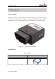
GV500 User Manual 2. Product Overview 2.1. Description GV500VC is based on the OBD II interface GPS vehicle tracking device, compact design and easy to install. GV500VC contains an OBD II connector which complies with J1962 standard, a 10PIN USB connector, an internal CDMA antenna, two internal GPS antenna and three LEDs. Figure 1. Appearance of GV500VC 2.2.
GV500 User Manual 2.3. Interface Definition The GV500VC has an OBD II connector. It contains power supply and interfaces of CAN BUS, K-line, L-line, J1850 BUS, GMLAN Single Wire CAN (GMW3089) and Ford Medium Speed CAN (MS CAN). The sequence and definition of the OBD II connector are shown in following figure: Figure 2.
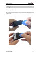
GV500VC User Manual 3. Getting Started 3.1. Opening the Case Insert the triangular-pry-opener into the gap of the case as shown below, push the opener up until the case unsnapped.
GV500VC User Manual Figure 3.
GV500VC User Manual 3.2. Closing the Case The battery is glued to shield cover, so before closing the case you should let the battery connector plugged in. The step of closing case is shown as following: Figure 4.
GV500VC User Manual 3.3. Installing the Internal Backup Battery Figure 5. Backup Battery Installation There is an internal backup Li-ion battery.
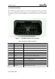
GV500VC User Manual 3.4. Device Status LED LED Device status LED status CEL (note1) Device is searching CDMA2000 1x network Fast flashing (Note3) Device has registered to CDMA2000 1x network. Slow flashing (Note4) Figure 6.
GV500VC User Manual GPS (note 2) OBD (note 2) GPS chip is powered off OFF GPS sends no data or data format error. Slow flashing GPS chip is searching GPS info. Fast flashing GPS chip has gotten GPS info. ON No external power and internal battery voltage is lower than 3.46V. GV500VC is power off. OFF No external power and internal battery voltage is below 3.
GV500VC User Manual 4. OBD II-related features 4.1. Communication Protocols GV500VC could monitor the OBD II system via not only all legislated OBD II protocols which defined by SAE but also some non-legislated OBD protocols. The list of protocols is shown as follow: Table 6: Communication Protocols List No. Protocol Comment 1 J1850 PWM 41.6kb/s FORD 2 J1850 VPW 10.
GV500VC User Manual 2) 3) 4) 5) 6) 7) 8) 9) 10) 11) 12) 13) OBD Power Voltage Parameter identification (PID) Revolutions per minute of the engine (RPM) Vehicle speed Engine Coolant Temperature Fuel Consumption Distance Statistics Malfunction Indicator Lamp (MIL) Diagnostic Trouble Codes (DTC) Throttle Position Engine Load Fuel Level Input Note: 1 - The VIN is the unique identifier of Vehicle.
GV500VC User Manual —Increase the separation between the equipment and receiver. -Connect the equipment into an outlet on a circuit different from that to which the receiver Is connected. —Consult the dealer or an experienced radio/TV technician for help.