
User`s manual

Quatech SDS Quick Start Guide Quatech SDS Quick Start Guide
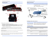
Identifying parts Making connections
You can easily connect each serial port on your SDS
to any serial device that you want to make accessible
to an Ethernet network.
Data LEDs
Power LE
Power Jack
D
Figure 1 - Connecting an SDS to a serial device
Step 3
–
Insert the power
source jack into the power plug
on the back of the SDS and
t
hen plug the power source into
a wall socket. Next you’ll install
t
he device drivers.
Electrical
outlet
Serial
cable
The SDS has several indicator LEDs:
B Power (blue) – indicates when the SDS has line power
B Data (red/green) – indicates serial port data activity by blinking red for RS-232 or green for RS-422/485
B Status (green) - indicates when the embedded processor is up and running.
B Link (green) - indicates when a network link has been established; located in the Ethernet connector
B Speed (amber) – differentiates between 100Base-T (glowing) and 10Base-T (off) Ethernet connection
speeds; located in the Ethernet connector
The DB-9 serial port(s) connect to your serial device(s) and can support RS-232, RS-422 or RS-485
connections. They are located either to the left, to either side of the Ethernet port, or on the front panel,
depending on the model.
The RJ-45 Ethernet jack connects the SDS to the Internet or to your Intranet. It has two small status LEDs: Link
(green) and Speed (amber).
The power jack should be connected to a +5V power source, as provided with the SDS.
The Reset button puts the SDS through a reset cycle and can also restore the SDS to the factory default settings.
The information label (not shown) is on the bottom of the SDS. It includes the MAC address, serial number,
certifications and connector pinout diagram.
Power LED
Data LED
Power Jack
Speed LED
Link LED
Ethernet Jack
Serial Port
Status LED
Reset Button
SDS
Speed LED
Link LED
Reset Button
Ethernet Jack Serial Ports Status
LED
Serial device
10/100
Ethernet
connection
Step 1
-
Make sure the serial
device is turned off and then
connect a serial cable between
t
he SDS and the serial device.
Step 2
-
Connect an Ethernet cable between your
Ethernet outlet and the 10/100 port on the SDS.
Power
source
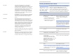
Enabling wireless device servers
Quatech’s wireless Device Servers need to have a
wireless network connection established before
they can be configured for use. To enable the
wireless connection, follow the steps below.
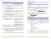
Note: To install an SDS
using a wired Ethernet
connection, skip to the
“Installing the Windows
device drivers” section.
December 2006 100-2000-163 Page 5
Step Procedure Description
Step 1
Connect the Ethernet port on your
SDS either to the NIC port on your
computer or to a switch/hub.
Use a CAT5 or better Ethernet cable
to attach the SDS.
Step 2
Connect power to the SDS.
Step 3
Confirm that the SDS is ready to
proceed.
The Status, Power and Link LEDs
should all glow steadily after a
moment.
Step 4
Insert the Quatech SDS installation
CD-ROM into your CD-ROM drive.
If the CD-ROM does not launch
automatically, select Start – Run
from the Task bar, browse to the CD-
December 2006 100-2000-163 Page 4