ESC-100 Eight Channel RS-232 Asynchronous Communications Adapter for PCI bus User's Manual QUATECH, INC. 5675 Hudson Industrial Parkway Hudson, Ohio 44236 TEL: (330) 655-9000 FAX: (330) 655-9010 http://www.quatech.
WARRANTY INFORMATION Quatech, Inc. warrants the ESC-100 to be free of defects for five (5) years from the date of purchase. Quatech, Inc. will repair or replace any board that fails to perform under normal operating conditions and in accordance with the procedures outlined in this document during the warranty period. Any damage that results from improper installation, operation, or general misuse voids all warranty rights. Please complete the following information and retain for your records.
(c) 1998 - 2004, Quatech, Inc. NOTICE The information contained in this document cannot be reproduced in any form without the written consent of Quatech, Inc. Likewise, any software programs that might accompany this document can be used only in accordance with any license agreement(s) between the purchaser and Quatech, Inc. Quatech, Inc. reserves the right to change this documentation or the product to which it refers at any time and without notice.
Declaration of Conformity Manufacturer's Name: Quatech Inc.
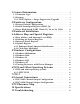
1 General Information ........................................ 1.1 Connector Type . . . . . . . . . . . . . . . . . . . . . . . . . . . . . . . . . . . . . . . . . . . . . . . . 1.2 Features . . . . . . . . . . . . . . . . . . . . . . . . . . . . . . . . . . . . . . . . . . . . . . . . . . . . . . . . 1.2.1 "IND" Option --- Surge Suppression Upgrade . . . . . . . . . . . 7 7 8 8 2 Hardware Configuration ................................. 9 2.1 Factory Default Configuration . . . . . . . . . . . . . . . .
1 General Information The Quatech, Inc. ESC-100 provides eight RS-232 asynchronous serial communication interfaces for IBM-compatible personal computer systems using the PCI expansion bus. The ESC-100 uses Quatech's new Enhanced Serial Adapter design. Legacy serial port data rates are limited to a maximum of 115,200 bits per second. Quatech Enhanced Serial Adapters can achieve data rates as high as 921,600 bits per second. As a PCI device, the ESC-100 requires no hardware configuration.
1.2 Features The standard ESC-100 implements each of its communication channels with a 16750 UART and uses standard line driver and receiver components. For improved performance and industrial-grade reliability, Quatech offers the following board upgrades: 1.2.1 "IND" Option --- Surge Suppression Upgrade The "IND" upgrade provides the protection essential for reliable use in an industrial environment.
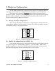
2 Hardware Configuration The ESC-100 is automatically configured at boot time by the computer's BIOS or operating system. There are no required switches or jumpers to set for installation. This chapter lists a number of optional jumper settings that control various hardware features. Jumpers J1-J4 are grouped together at the end of the board opposite the D-78 or RJ-11 connector. Any changes from the factory default should be made before installing the ESC-100 in the computer. 2.
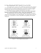
2.3 Force High-Speed UART Clock (X2, X4, or X8, J1-J3) These jumpers force an increase of the UART input clock frequency by a factor of two, four, or eight. This can allow legacy software to use baud rates above 115,200 bits per second. It is also useful if the serial port device driver does not directly support setting the higher baud rates through the Options Register (see page 9).
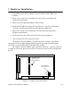
3 Hardware Installation 1. Turn off the power of the computer system in which the ESC-100 is to be installed. 2. Remove the system cover according to the instructions provided by the computer manufacturer. 3. Make any desired optional jumper setting changes. 4. Install the ESC-100 in any empty PCI expansion slot. The board should be secured by installing the Option Retaining Bracket (ORB) screw. 5. Replace the system cover according to the instructions provided by the computer manufacturer. 6.
4 Address Map and Special Registers This chapter explains how the eight UARTs and special registers are addressed, as well as the layout of those registers. This material will be of interest to programmers writing driver software for the ESC-100. 4.1 Base Address and Interrupt Level (IRQ) The base address and IRQ used by the ESC-100 are determined by the BIOS or operating system. Each serial port uses 8 consecutive I/O locations.
4.2 Enabling the Special Registers The ESC-100 contains two unique registers, an Interrupt Status Register and an Options Register. These registers are enabled when the SPAD jumper (J4) is removed (factory default). They replace the UART Scratchpad Register on accesses to register address 7. The Interrupt Status Register and Options Register are accessed through the scratchpad location of any UART. The DLAB bit of the UART (Line Control Register, bit 7) is used to select between the two registers.
4.4 Options Register The Options Register allows software to identify the ESC-100 as a Quatech Enhanced Serial Adapter. It also allows software to set the UART clock rate multiplier. Figure 9 shows the structure of the Options Register. The powerup default of the Options Register is all bits zero.
4.4.2 Clock Rate Multiplier A standard RS-232 serial port operates at a clock speed of 1.8432 MHz. In order to achieve higher data rates, Quatech Enhanced Serial Adapters can operate at two times, four times, or even eight times this standard clock speed. This is controlled by the clock rate multiplier bits in the Options Register. Software can determine the UART clock frequency by reading the clock rate multiplier bits RR1 and RR0 in the Options Register as shown in Figure 11.
5 Windows Configuration 5.1 Windows Millennium 1. After inserting the ESC 100 for the first time the "Add New Hardware Wizard" will begin. Select "Search for the best driver for your device.". Check the "Removable media" and "Specify location" box. Click the "Next" button. 2. 3. Window will locate the proper INF file and copy the file from the CD. Click the "Next" button. The final dialog screen will verify the file copy from the diskette. Click the "Finish" button.
5.2 Windows 2000 1. After inserting a ESC-100 for the first time, the "Add New Hardware Wizard will appear at start up. Click the "OK" button. 2. The following dialog box insert the Quatech COM CD (shipped with the device). Click the "OK" button. 4. The following dialog box will display the appropriate INF file on the CD in the drive. Click the "OK" button. 5. Window will copy the INF file from the diskette and display a final dialog indication that the process is complete. Click the "Finish" button.
5.3 Windows 98 1. After inserting a ESC-100 for the first time, the "Add New Hardware Wizard will appear at start up. Click the "Next" button. 2. Select "Search for the best driver for you device". Click the "Next" button. 3. On the next dialog, select the "CD-ROM DRIVE" check box. Insert the PCI Communication Drivers CD (shipped with the device) into the CD-ROM. Click the "Next" button.
4. The following dialog box will display the appropriate INF file on the CD in drive. Click the "Next" button. 5. Window will copy the INF file from the CD and display a final dialog indication that the process is complete. Click the "Finish" button. 5.4 Windows 1995 The following instructions provide step-by-step instructions on installing the ESC-100 in Windows 95 using the "New Hardware Found" wizard. 1.
are not required to select the file name. After finding the directory containing the INF files, Windows 95 will choose the correct file. 4. The "New Hardware Found" dialog box will appear again, this time for an "Unknown Device." 5. Again select the radio button for "Driver from disk provided by hardware manufacturer." Click the "OK" button to continue. 6. Another "Install From CD" dialog box will pop up. The path should already be pointing to the Quatech diskette. Click the "OK" button to continue. 7.
5.6 Viewing Resources with Device Manager The following instructions provide step-by-step instructions on viewing resources used by the ESC-100 in Windows using the "Device Manager" utility. Select Start|Help from within Windows for additional information on this utility. 1. Double click the "System" icon inside the Control Panel folder. This opens up the System Properties box. 2. Click the "Device Manager" tab located along the top of the System Properties box.
assigned to your ports by Windows 95. This name is required by a Windows 95 application when accessing a particular port. Windows maintains a registry of all known hardware installed in your computer. Inside this hardware registry Windows keeps track of all of your system resources, such as I/O locations, IRQ levels, and DMA channels. The "Add New Hardware Wizard" utility in Windows 95 was designed to add new hardware and update this registry.
6 DOS and Other Operating Systems 6.1 DOS and other operating systems The ESC-100 is not a direct drop-in replacement for a legacy serial port because its base address and IRQ cannot be fixed at values such as 3F8 hex, IRQ 4 (COM1) or 2F8 hex, IRQ 3 (COM2), etc. Rather, the system BIOS assigns the address and the IRQ in a plug-and-play fashion at boot time. Software which is to use the ESC-100 must be able to accommodate any valid assignments of these resources.
The QTPCI program is capable only of displaying the PCI configuration. It cannot be used to make changes. Quatech PCI Configuration Information Display Software Version 1.00 INSTRUCTIONS: -----------------------Press keys listed in the menu at the bottom of the screen. This program only displays information. It cannot make changes PCI BIOS detected, version 2.
I/O regions, etc. Pressing the "N" key will show similar information for all non-Quatech PCI devices in the system, including those devices integrated on the motherboard. In this example, the "Base addr 0" resource is reserved. For users interested in even more details, PCI BIOS information can be displayed by pressing the "B" key. Pressing the "I" key displays the PCI interrupt routing table. Quatech PCI Configuration Information Display Software Version 1.
7 OS/2 The OS/2 device driver supports up to 32 serial ports in a system. Installation is a manual, but simple, process. Please refer to the read me documentation included on the Quatech COM CD with the device driver for full installation and configuration details.
8 External Connections RS-232-C devices are classified by their function as either Data Terminal Equipment (DTE) or Data Communication Equipment (DCE). Generally, data terminal equipment is defined as the communication source and data communication equipment is defined as the device that provides a communication channel between two DTE-type devices.
8.1 ESC-100D Channel Output Configuration The ESC-100D connects to peripheral equipment through a single female D-78 connector, or using the adapter cable, eight male D-25 connectors. The standard serial port connections are listed in Figure 18. Unlisted pins are not used and not connected.
1 40 21 2 60 41 22 3 4 61 42 23 62 13 63 12 64 11 65 10 66 9 67 8 68 7 69 6 70 5 71 4 72 3 43 24 5 44 25 6 45 26 7 46 27 8 47 28 9 48 29 10 49 30 11 50 31 12 51 32 13 52 33 14 53 34 15 73 54 35 16 17 74 24 23 22 21 20 19 18 17 16 15 2 14 1 55 36 56 37 18 75 76 38 D-25 connectors on the adapter cable 57 19 77 58 39 20 25 59 78 D-78 connector Dashed lines delineate channels Pins 25, 30, 35, 64, 69, 74 unused Figure 19 --- ESC-100D Output Conn
8.2 ESC-100M Channel Output Configuration The ESC-100M connects to peripheral equipment through RJ-11 connectors, or using the optional adapter cables, male D-25 connectors. When the RJ-11 connector is converted to a D-25 connector, the adapter cables must be assembled with respect to either a DTE or DCE configuration. The standard serial port connections are listed in Figure 20.
The AUXIN and AUXOUT signals on the RJ-11 connector must be determined as well. Either CTS or DSR may be received on AUXIN. Either RTS or DTR may be transmitted on AUXOUT. The decision of which signals to use is made separately for each channel as shown in Figure 22 below. The Ring Indicator (RI) signal is tied permanently to DSR.
9 PCI Resource Map Listed below are the PCI resources used by the ESC-100. Such information may be of use to customers writing their own device drivers or other custom software. A detailed description of the ESC-100's UARTs is available on the Quatech web site. (all numbers in hex) PCI Vendor ID: 0x135C Quatech, Inc.
10Specifications Bus interface PCI, 32-bit bus, 5-volt only IBM-compatible computers Dimensions: approx. 6.5" x 4.
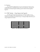
Data Rate (kbaud) 921.6 460.8 230.4 115.2 4% trans time N/A 100 330 800 Maximum Load (pF) 10% 15% 20% trans trans trans time time time 100 300 430 430 670 900 900 1100 1630 1570 3300 4300 25% trans time 470 1100 2000 4800 Note 1: The signal transition time ratio is defined as the percentage of the unit interval or bit time (the inverse of the data rate) that is occupied by the signal transitioning from -3V to +3V.
11 Troubleshooting Listed here are some common problems and frequent causes of those problems. If the information here does not provide a solution, contact Quatech technical support. Any unauthorized repairs or modifications will void the ESC-100's warranty. Computer will not boot up. 1. Is the ESC-100 properly inserted? Remove the card and try again. Perhaps try a different expansion slot. 2. Ensure that an ISA-bus card is not using the same IRQ that the PCI BIOS tries to assign to the ESC-100.
ESC-100D/M User's Manual Revision 1.