DSP-100 Dual Channel RS-232 PCMCIA Asynchronous Adapter for PCMCIA Card Standard compatible machines User's Manual INTERFACE CARDS FOR IBM PC/AT AND PS/2 QUATECH, INC. 662 Wolf Ledges Parkway Akron, Ohio 44311 TEL: (330) 434-3154 FAX: (330) 434-1409 www.Quatech.
(This page intentionally left blank.
Warranty Information Quatech Inc. warrants the DSP-100 to be free of defects for five (5) year from the date of purchase. Quatech Inc. will repair or replace any adapter that fails to perform under normal operating conditions and in accordance with the procedures outlined in this document during the warranty period. Any damage that results from improper installation, operation, or general misuse voids all warranty rights.
Declaration of Conformity Manufacturer's Name: Quatech Inc.
Table of Contents 1 . Introduction . . . . . . . . . . . . . . . . . . . . . . . . . . . . . . . . . . . . . . . . . . . . . . . . . . . . . . . . 1 2 . DOS / Windows 3.x Installation . . . . . . . . . . . . . . . . . . . . . . . . . . . . . . . . . 3 2.1 DSP-100 Client Driver for DOS . . . . . . . . . . . . . . . . . . . . . . . . . . . . . . . . . . . 4 2.1.1 Client Driver Installation . . . . . . . . . . . . . . . . . . . . . . . . . . . . . . . . . . . . 4 2.1.2 Command Line Options . . . . . . . . . .
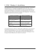
12 . Specifications . . . . . . . . . . . . . . . . . . . . . . . . . . . . . . . . . . . . . . . . . . . . . . . . . . . .
1. Introduction The DSP-100 provides two independent RS-232 asynchronous serial communications interfaces for systems equipped with PCMCIA Type II and/or Type III expansion sockets. The DSP-100 is a PCMCIA Type II (5 mm) card and is PCMCIA PC Card Standard Specification 2.1 compliant.
(This page intentionally left blank.
2. DOS / Windows 3.x Installation Two configuration software programs are provided with the DSP-100: a Client Driver, DSP100CL.SYS, and a card Enabler, DSP100EN.EXE. Both of these programs are executed from DOS (before entering Windows) and allow operation of the DSP-100 in both the DOS and Windows 3.x environments. For optimal operation, however, the Client Driver is the preferred method of installation and configuration. The table below highlights the differences between these programs.
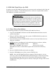
2.1 DSP-100 Client Driver for DOS In order to use the DSP-100 Client Driver, the system must be configured with Card and Socket Services software. Card and Socket Services software is not provided with the DSP-100 but is available from Quatech. IMPORTANT: Some versions of Card and Socket Services dated before 1993 do not support general purpose I/O cards.
7. Reboot the system and note the message displayed when the DSP-100 Client Driver is loaded. If the Client Driver reports an "invalid command line option", correct the entry in the CONFIG.SYS file and reboot the system again. If the Client Driver reports "Card and Socket Services not found", a version of Card and Socket Services must be installed on the system or the DSP-100 Enabler program must be used to configure the adapter.
U instructs the Client Driver to disable the DSP-100's interrupt status register and enable the Scratchpad registers of the individual UARTs. This option is only required in very rare cases where an application program requires access to the UART's Scratchpad register. If this option is omitted, the DSP-100's interrupt status register is enabled and the UARTs' Scratchpad registers are disabled. 2.1.2.1 Example 1 DEVICE = C:\DSP-100\DSP100CL.SYS In example 1, no command line arguments are specified.
2.1.2.3 Example 3 DEVICE = C:\DSP-100\DSP100CL.SYS (s0,b300,i5) In example 3, a single command line argument is provided. The Client Driver will attempt to configure a DSP-100 inserted into socket 0 with a base address of 300H and IRQ 5. If address 300H or IRQ 5 is unavailable, the DSP-100 will not be configured. In addition, if a DSP-100 is inserted into any other socket, it will not be configured. If the Client Driver can successfully configure the DSP-100 its interrupt status register will be enabled.
2.1.2.6 Example 6 DEVICE = C:\DSP-100\DSP100CL.SYS (b300,i5) ( ) (i10) In example 6, the three command line arguments of example 5 have been rearranged. The Client Driver will first attempt to configure a DSP-100 inserted into any socket with a base address of 300H and IRQ 5. If address 300H or IRQ 5 is unavailable, the Client Driver will proceed to the second command line argument and attempt to configure the card with a base address and IRQ assigned by Card and Socket Services.
2.1.3 Common Problems Generic Client Drivers: Many Card and Socket Services packages include a generic client driver (or SuperClient) which configures standard I/O devices. If one of these generic client drivers is installed, it may configure the DSP-100 causing the DSP-100 client driver to fail installation. In these cases, the user should do one of the following: 1. modify the operation of the generic client driver to disable the configuration of modem/serial port cards.
2.2 DSP-100 Enabler for DOS For systems that are not operating PCMCIA Card and Socket Services software, the DSP-100 DOS Enabler may be used to enable and configure the adapter. This Enabler, DSP100EN.EXE, will operate on any DOS system using an Intel 82365SL or PCIC compatible PCMCIA host adapter including the Cirrus Logic CL-PD6710 / 6720, the VLSI VL82C146, and the Vadem VG-365 among others.
2.2.1 Command Line Options To configure a DSP-100 in the system, the Enabler requires one command line argument from the user to determine the configuration of the card. This argument must be enclosed in parenthesis and within the argument, any or all of the following parameters may be specified using a comma (no spaces) to separate each parameter: Ssocket specifies which PCMCIA socket the DSP-100 must be inserted into for this configuration argument to be used. socket must be in the range 0 - 15.
R instructs the Enabler to release the resources previously allocated to the DSP-100. When the 'R' option is used, any settings specified by the 'B', 'I', and 'U' options are ignored. 2.2.1.1 Example 1 DSP100EN.EXE In example 1, no command line argument is specified. The Enabler will report an error and display the proper usage of the command. 2.2.1.2 Example 2 DSP100EN.
2.2.1.4 Example 4 DSP100EN.EXE (s0,b300,i3,wd8) In example 4, the Enabler will configure the DSP-100 in socket 0 with a base address of 300H and IRQ 3 using a configuration memory window at segment D800. The DSP-100's interrupt status register will be enabled. 2.2.1.5 Example 5 DSP100EN.EXE (s0,b300,i5,r) In example 5, the Enabler will release the configuration used by the DSP-100 in socket 0 using a configuration memory window at segment D000.
2.2.2 Common Problems Memory Range Exclusion: The Enabler requires a region of high DOS memory when configuring a DSP-100. This region is 1000H bytes (4KB) long and by default begins at address D0000H (the default address may be changed using the "W" option). If a memory manager such as EMM386, QEMM, or 386Max is installed on the system, this region of DOS memory must be excluded from the memory manager's control.
3. Windows 95 Installation To allow easy configuration of the DSP-100, an Windows 95 "INF" configuration file has been written for the hardware. This configuration file supports the DSP-100 in both addressing modes: block mode and “com” mode. 3.1 Installing a DSP-100 Under Windows 95. 1. Insert the DSP-100 into any available PC Card socket. 2. The first time a new PC Card type is installed the New Hardware Found window opens.
3.2 DSP-100 Resource Settings in Windows 95 Windows 95 maintains a registry of all known hardware installed within the computer. Inside this hardware registry Windows 95 keeps track of all the computer's resources, such as base I/O addresses, IRQ levels, and DMA channels. In the case of a PC Card (PCMCIA) type board, Windows 95 configures the new hardware using free resources it finds within the hardware registry, and updates the registry automatically.
6. View the Properties dialog for each COM port and examine the Resources allocated to each port. Inside the Resource allocation window two of the COM ports will identify the QuatechInc-PCMCIA Dual RS-232 Serial Port Card as the parent device. The Input/Output Range and Interrupt Request resource allocations for these two COM ports will also match the resource allocations of the DSP-100 “parent device”. Figure 2. Windows 95 Device Manager 7. Use the COM Port device names (COM2, COM4, etc.
3.2.2 Changing Resource Settings with Device Manager The DSP-100's serial ports are addressable in two modes: block mode, and “COM” mode (see Chapter 5: Hardware Information). The DSP-100 is addressable in either mode from Windows 95. 1. Start the Windows 95 Device Manager. 2. Double click on the hardware class Multi-function Adapters to list hardware devices in the class. 3. The DSP-100 “parent device” belongs to this hardware class.
6. Select a Basic Configurations that displays "No conflicts" in the bottom display region titled Conflicting Device List from the drop down list. Some applications may not be able to access ports higher than COM4. To use the DSP-100 PCMCIA serial ports with these applications you might be forced to remove other serial communications devices from your system. Figure 4. Windows 95 Resource Allocation 7.
8. To modify the Interrupt Request setting click the resource name and click the Change Setting button. An Edit Resource window will open up. Inside this window click on the up/down arrows to the right of the Interrupt Request value. This scrolls you through all of the allowable resources for your hardware. Pay attention to the conflict information at the bottom of the window. Do not select a value that causes a conflict with any other installed hardware. 9.
4. Windows 98/Millennium (ME) Installation To allow easy configuration of the DSP-100, an Windows 98/ME "INF" configuration file has been written for the hardware. This configuration file supports the DSP-100 in both addressing modes: block mode and “com” mode. 4.1 Installing a DSP-100 Under Windows 98/ME. 1. Insert the DSP-100 into any available PC Card socket. 2. The first time a new PC Card type is installed the New Hardware Found window opens.
4.2 DSP-100 Resource Settings in Windows 98/ME Windows 98/ME maintains a registry of all known hardware installed within the computer. Inside this hardware registry Windows 98/ME keeps track of all the computer's resources, such as base I/O addresses, IRQ levels, and DMA channels. In the case of a PC Card (PCMCIA) type board, Windows 98/ME configures the new hardware using free resources it finds within the hardware registry, and updates the registry automatically.
6. View the Properties dialog for each COM port and examine the Resources allocated to each port. Inside the Resource allocation window two of the COM ports will identify the QuatechInc-PCMCIA Dual RS-232 Serial Port Card as the parent device. The Input/Output Range and Interrupt Request resource allocations for these two COM ports will also match the resource allocations of the DSP-100 “parent device”. Figure 2. Windows 98/ME Device Manager 7. Use the COM Port device names (COM2, COM4, etc.
4.2.2 Changing Resource Settings with Device Manager The DSP-100's serial ports are addressable in two modes: block mode, and “COM” mode (see Chapter 5: Hardware Information). The DSP-100 is addressable in either mode from Windows 98/ME. 1. Start the Windows 98/ME Device Manager. 2. Double click on the hardware class Multi-function Adapters to list hardware devices in the class. 3. The DSP-100 “parent device” belongs to this hardware class.
6. Select a Basic Configurations that displays "No conflicts" in the bottom display region titled Conflicting Device List from the drop down list. Some applications may not be able to access ports higher than COM4. To use the DSP-100 PCMCIA serial ports with these applications you might be forced to remove other serial communications devices from your system. Figure 4. Windows 98/ME Resource Allocation 7.
8. To modify the Interrupt Request setting click the resource name and click the Change Setting button. An Edit Resource window will open up. Inside this window click on the up/down arrows to the right of the Interrupt Request value. This scrolls you through all of the allowable resources for your hardware. Pay attention to the conflict information at the bottom of the window. Do not select a value that causes a conflict with any other installed hardware. 9.
5. Windows 2000 Installation To allow easy configuration of the DSP-100, an Windows 2000 "INF" configuration file has been written for the hardware. This configuration file supports the DSP-100 in both addressing modes: block mode and “com” mode. 5.1 Installing a DSP-100 Under Windows 2000. 1. Insert the DSP-100 into any available PC Card socket. 2. The first time a new PC Card type is installed the New Hardware Found window opens.
5.2 DSP-100 Resource Settings in Windows 2000 Windows 2000 maintains a registry of all known hardware installed within the computer. Inside this hardware registry Windows 2000 keeps track of all the computer's resources, such as base I/O addresses, IRQ levels, and DMA channels. In the case of a PC Card (PCMCIA) type board, Windows 2000 configures the new hardware using free resources it finds within the hardware registry, and updates the registry automatically.
Windows 2000 Device Manager 5.2.2 Changing Resource Settings with Device Manager The DSP-100's serial ports are addressable in two modes: block mode, and “COM” mode. The DSP-100 is addressable in either mode from Windows 2000. 1. Start the Windows 2000 Device Manager. 2. Double click on the hardware class Quatech Multi-Port Serial Devices to list hardware devices in the class. 3. The DSP-100 “parent device” belongs to this hardware class.
4. Open the Properties dialog for the DSP-100 device, then click the Resources tab to view the Input/Output Range and Interrupt Request resource allocations. 5. Select a Basic Configurations that displays "No conflicts" in the bottom display region titled Conflicting Device List from the drop down list. Some applications may not be able to access ports higher than COM4.
7. To modify the Interrupt Request setting click the resource name and click the Change Setting button. An Edit Resource window will open up. Inside this window click on the up/down arrows to the right of the Interrupt Request value. This scrolls you through all of the allowable resources for your hardware. Pay attention to the conflict information at the bottom of the window. Do not select a value that causes a conflict with any other installed hardware. 8.
6 Windows NT 6.1 Installing DSP-100 Under Windows NT To allow easy configuration of the DSP-100 the Quatech Device Manager for Windows NT has been written for the hardware. This configuration utility supports the DSP-100 only in block addressing mode. To begin the installation, open Windows Explorer and search for the ‘Setup.exe’ command to install the Quatech Device Manager. (D:\Serial Port Adapters\Drivers\Windows NT 4.0 for PCI, PCMCIA,ISA).
1.
2. Click the ‘Add’ button at the bottom of the Quatech Device Manager Window. 3. Follow the steps for the ‘Add Quatech Hardware Wizard’.
4. Complete the final steps of the installation, insert the PCMCIA Card and reboot the computer. v Additional help is available online The DSP-100 PC Card should now be configured. In the future, Windows NT will automatically recognize and configure the DSP-100. Note: Windows NT does not support ‘Plug and Play’ for PCMCIA cards. The PCMCIA Card must be inserted prior to starting Windows NT and can not be removed and reinserted while Windows NT is running.
7 Windows CE The Quatech PCMCIA Windows CD installation copies a multiple device-specific .cab files and the ini file to your desktop computer and launches the Application Manger (which resides on the user's desktop computer as a result of installing Active Sync) with the Application Manager .ini file as a parameter. This in turn will install the driver onto the Windows CE connected device or if not connected will install it on the next device connection to the desktop. 1.
3. The setup program will copy the files to predetermined location, which can be changed by the user. Click next to proceed.. Installation is now complete. In the event that installation process took place with out having the Windows CE device connected to the computer and the install program will prompt the user that on the next on the next connection the device will complete the installation. Choose ‘Yes’ on the following window and you installation is now complete.
8 OS/2 Installation In order to use the DSP-100 Client Driver for OS/2, the system must be configured as follows: 1. The system must be running OS/2 version 2.1 or later. 2. OS/2 PCMCIA Card and Socket Services support must be installed. If PCMCIA support was not selected when OS/2 was installed, it can be added using the Selective Install facility in the System Setup folder. On OS/2 2.1 and 2.11, Socket Services must be added separately.
8.1 Command Line Options The DSP-100 Client Driver for OS/2 supports two methods of configuration: using "system assigned" resources and using "user assigned" resources. Both options provide full PCMCIA compliance and functionality (including "Hot-swapping") but each has some advantages and disadvantages as discussed in the following sections. 8.1.
8.1.2 Configuring With "User Assigned" Resources As mentioned in the previous section, allowing the OS/2 Plug-and-Play system to assign the hardware resources to the DSP-100 is ideal for OS/2 programs but can be a problem if DOS and/or Windows applications will be accessing the serial ports. This is because most DOS applications write directly to the communications hardware and the Windows' Control Panel also wants to know the hardware configuration of the serial ports.
8.1.2.2 Example 2 DEVICE=C:\DSP-100\DSP100.SYS (7,120,15) (3,300,4) In example 2, the Client Driver will attempt to configure the DSP-100 as COM3 and COM4 using I/O address 300-30F hex and IRQ 4. If COM3 or COM4 already exists, or if the I/O address or IRQ resources are already in use, the Client Driver will attempt to configure the DSP-100 as COM7 and COM8 using I/O address 120-12F hex and IRQ 15.
8.2 Monitoring The Status Of PCMCIA Cards OS/2 Warp provides a utility called "Plug and Play for PCMCIA" that can be used to monitor the status of each PCMCIA socket. In OS/2 2.1, this utility is called "Configuration Manager". When a DSP-100 is inserted, the Card Type for the appropriate socket will display "Multi-Function". If the card is successfully configured, the Card Status will display "Ready". If the card cannot be configured, the Card Status will be "Not Ready".
Parameter Overlapping: When installing the DSP-100, each command line argument specifies the first of two COM ports. If these arguments overlap, the Client Driver will not load. For example, it is illegal to specify DSP100.SYS COM3 COM4 because the first argument requests COM3 - COM4 and the second argument specifies COM4 - COM5. Insufficient Number Of Command Line Arguments: The DSP-100 command line must contain at least one command line argument for each DSP-100 to be installed.
9. Unix Support The DSP-100 and other Quatech asynchronous serial communications interface products are supported in the UNIX operating system by Quatech’s UNIX Enhanced Serial Device Driver. This driver is not included with the DSP-100, but may be purchased separately. 9.
(This page intentionally left blank.
10. Hardware Information The DSP-100's two asynchronous serial ports are implemented using 2 standard 16C550 UARTs. Each of these UARTs requires 8 bytes of I/O space. The DSP-100's serial ports are addressable in two modes: 1. 'Block Mode' : The two serial ports are configured in one 16-byte continuous block of I/O address space. The block must begin on an even 16-byte (10H) boundary (e.g. 300H, 310H, 320H, etc.).
DSP-100 User's Manual 47
11. External Connections An adapter cable is included with the DSP-100 to convert the 25-pin output connector into 2 standard D-9 male RS-232 connectors as shown in the figure below. Port A Port B Figure 7. DSP-100 Adapter Cable. Gnd 5 DTR 4 TxD 3 RxD 2 DCD 1 9 RI 8 CTS 7 RTS 6 DSR D-9 Male Connector Figure 8. Standard RS-232 Signal Assignment.
(This page intentionally left blank.
12. Specifications Bus Interface PCMCIA PC Card Standard 2.1 compliant Physical Dimensions Type II PCMCIA card (5mm) Maximum Baud Rate 120K Power Requirements 45.87 mA (maximum) +5 volts Connector Adapter to 2 standard male D-9 DSP-100 User's Manual 35.
DSP-100 User's Manual Revision 2.