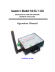
Quatech Model SS-BLT-400 Bluetooth to RS-232/422/485 Isolated Converter Operation Manual First Edition, Jun 2008
Table of Contents 1. Introduction ……………………………………………… 2. Package checklist …………………………………………… 3. Product Specification …………………………………… 4. Product Panel Views Description …………………… Product Views …………………………………… 2 3 4 6 6 DC-In Power Outlet ………………………………………… 6 Antenna Connecter …………………………………………… 7 Serial I/O Port of RS-232&RS-422/485 Terminator Set Button …………………… …………………………………………………… …………………………………………………… LED Indicators ……………………………………………… 5. Hardware Installation …………………………………… 6.
1 Introduction Thank you for your purchase of the Bluetooth To Serial Adapter. Featuring Bluetooth wireless technology, it is for replacement of standard RS232 or industrial RS422/485 cable perfectly, with standard RS232 and industrial RS422/485 interfaces, so can be easily adopted for industrial machines with RS232 or RS422/485 interfaces. The Bluetooth To Serial Converter is compatible with all Bluetooth V.2.0-certified and is backward compatible with v1.1/1.2 devices.
2 Package checklist This Bluetooth To Serial Converter is shipped with the following items: 1 unit of Bluetooth To Serial Converter 1 unit of Power Adaptor (9V DC, 200mA) User Operation Manual Software CD NOTE: Notify your sales representative if any of the above items is missing or damaged 3
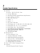
3 Product Specification Serial Port No. of Ports : RS-232 / 422 / 485 * 1 Port ● Port Type : DB9 Female ● Built-in RS-422/RS-485 Terminal Resister (Surge Protection) ● Speed : 1200 bps~115.
Environment : Operating Temperature: 0℃~60℃ Storage Temperature : -25℃~70℃ Dimensions : 90 * 65 * 27 mm ( W * D * H ) WEIGHT : 200 gm Regulatory Approvals : EMC : FCC Class A, CE Class A WARRANTY : 1 year RoHS 5
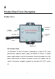
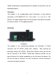
4 Product Panel Views Description Product Views Serial I/O Port RS422/485 DC-In Power Outlet Sync Button Serial I/O Port RS-232 Antenna LED Indicators DC-In Power Outlet This Bluetooth To Serial Converter is powered by a single 9V DC (Inner positive/outer negative) power supply and 200mA of current. A suitable power supply adapter is part of the package. Connect the power line to the power outlet beside of antenna connector and put the adapter into the socket.
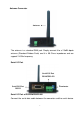
Antenna Connector Antenna The antenna is a standard SMA jack. Simply connect it to a 2.0dBi dipole antenna (Standard Rubber Duck) and it is 50 Ohms impedance and can support 2.4GHz frequency. Serial I/O Port Serial I/O Port RS-485/RS-422 Serial I/O Port RS232 Terminator Serial I/O Port of RS232&RS422/485 Connect the serial data cable between the converter and the serial device.
Follow the parameter setup procedures to configure the converter (see the following chapters). Terminator The purpose is for compensating signal attenuation in long distance connection at RS-485/RS-422 I/O. If the switch 1 & 2 are set in “ON” position, the signal compensation will be activated. To disable the function, just to push switch 1 & 2 to opposite position. Set Button Set Button The purpose is for synchronizing between this Bluetooth To Serial Converter and “BT RS232 Config Tool” software.
LED Indicators SYS (Red): It is the power indicator, when the power is on then the LED will blink once per second. Pair (Green): Before connecting to synchronize between the device and the “BT RS232 Config Tool” software, the green LED will be blinking After connecting to synchronize between the device and the “BT RS232 Config Tool” software, the green LED (Pair) will be on RX (Red): Data received indicator (When data are received from the network, the LED will be on.
5 Hardware Installation 1. Connect this Bluetooth To Serial Converter to COM Port of PC and then to connect DC power adapter and jack into power outlet and DC-in outlet. You will see the red LED is going to be on and the green LCD will be blink. 2. After running the BT RS232 Config Tool and finish configuration. Click the icon of “Connect” in tool software and press the set button of this Bluetooth To Serial Converter immediately. 3. The green LED will be turn into on.
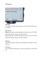
6 BT RS232 Config Tool Installation & Setup When setting up this Bluetooth to Serial Converter for the first time, you have to install and run “BT1.exe” as “BT RS232 config tool” first in your computer device. The utility CD is enclosed in the device box. Before you use this Bluetooth to Serial Converter, you have to pair it with another Bluetooth to Serial Converter. All the Bluetooth to Serial converters must be configured first before you use it.
BT RS232 Config Tool Parameters Configuration After double click the icon of BT1 as “BT RS232 Config Tool”, the configuration screen will be pop-up as the above picture. A. COM Port Select COM port number, you have to avoid the port conflict with other device in computer and use available port number B. Device Name Select device name is for identify each one device and you can follow the name by tool access or retyping the new name by yourself. C.
E. PIN Code PIN code is for the purpose of security consideration during as like a pass key. Device uses this “PIN Code” to identify during connecting and communication. F. Role Role is for identifying a role of the device as a master or slave. The item of “Role” is chose “Master”. The device will be play like a DTE mode - Data Terminal Equipment (such as a PC). If the item of “Role” is chose “Slave” and the device will be play like a DCE - Data Communication Equipment (such as a Modem).
Apply “Connect” After finish the parameters configuration, click the icon of “Connect” in BT RS232 Config Tool screen and meanwhile press the Synchronous button immediately on the left side of the device. And then the next screen of parameters configuration is pop-up. The icon of “Connect” is changed to “Disconnect” and two icons will be turned into active mode on the bottom of the BT RS232 Config Tool screen.
Apply “Write” To click the item of “Write”, the meaning is to save all parameters after configuring into the “BT RS232 Config Tool”. Apply “Read” To click the item of “Read”, the meaning is to load all parameters as last time saving from the “BT RS232 Config Tool”. The local address will be updated the real device address at first time.
Appendix A Pin outs and Connector □□ DC Power outlet □□ RS-232 Pin Assignment The pin assignment scheme for a 9-pin male connector on a DTE is given below.
□□ RS-422/485 Pin Assignment The pin assignment scheme for a 4-pin RS-422 is given below.