
Specifications


1.800.553.1170
Communication Overview
15
COM
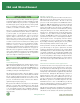
The high speed data transfers across the PCI bus limits the number
of PCI expansion slots that can be built into a single bus to 3 or
4, as opposed to the 6 or 7 available on the ISA bus. To expand
the number of available expansion slots, PCI-to-PCI bridges are
used. (See diagram left.) These bridges create a primary and a
secondary PCI bus, each of which is electrically isolated from the
other. Multiple bridges can be cascaded, theoretically allowing
unlimited numbers of PCI slots to be configured in a single system.
(Practically, it is important not to overload the CPU, as adding
too many devices via expansion slots could considerably
compromise system bandwidth.) The bridge enables bus transfers
to be forwarded upstream or downstream, from one bus to
another until the target/destination is reached.
Flexible Bus Mastering
Several pins on the PCI bus are reserved for implementing bus
mastering. This means that any PCI device can take control of
the bus at any time, even allowing it to shut out the CPU. Devices
use bandwidth as available, and can potentially use all bandwidth
in the system if no other demands are made for it.
Bus mastering
works by sending Request signals to the Central Resource
(
circuitry on the motherboard shared by all bus devices) when a
device wants control of the bus, and when that control is ceded
a Grant signal is received by the device. This flexible approach,
which separates the arbitration and control signals (they were
bussed together on MicroChannel and ISA), allows a computer
designer greater control over the arbitration process.
Interrupt sharing on the PCI bus is also implemented to provide
maximum flexibility. Four level-sensitive interrupts are located
on the bus at pins A6, B7, A7 and B8, each of which can be
assigned to from one to 16 separate devices. These interrupts
can be activated at any time because they are not synchronized
with the other signals on the bus. The PCI specification does
not define how interrupts are to be shared. The process is
implemented on a case-by-case basis by the motherboard
manufacturer. For instance, Quatech multi-port serial PCI boards
require only one slot to provide up to eight serial ports. These
eight ports share a single interrupt, and our boards provide an
interrupt status register that will indicate which of the eight ports
triggered an interrupt.
Looking Ahead
The PCI-X specification is a high-performance enhancement to
the PCI bus specification. It doubles the maximum clock
frequency that can be used by PCI devices from 66 MHz to
133Mhz, thus enabling communication at speeds over 1 Gbyte/
sec. It also improves the efficiency of the PCI bus itself and the
devices attached to it, by providing new features such as split
transactions and transaction byte counts. PCI-X was developed
for applications such as Gigabit Ethernet, Fibre Channel and other
Enterprise server applications.
PCI Specification 3.0 is due for release in late 2001. This
specification is largely based on PCI-X, and is intended to solidify
the extensive changes made to PCI since the release of
Specification 2.1. It also addresses a number of power
issues designed to make PCI systems more efficient.
Clearly, traditional PCI add-in boards are not practical for
portable systems or for systems that use small-size cases.
Two new standards have been developed that address
these issues: Low Profile PCI and Mini-PCI. Low Profile PCI
was designed to provide greater flexibility in desktop and server
environments. The card is mechanically similar to a standard PCI
card, but uses a shorter card and a different mounting bracket.
(See the figure below).
Low Profile PCI cards are designed to fit into systems as low as
PCI Expansion Board
Low Profile PCI
Expansion Board
(Relative sizes for PCI and Low Profile PCI boards)
Continued on page 18