
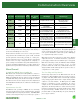
Specifications


www.quatech.com
14
PCI
A New Standard
First released in 1992, the Peripheral Component Interface (PCI)
has rapidly evolved into a viable replacement for the ISA bus,
and is the most commonly used method for adding boards to a
PC. It solves many of the problems with older architectures,
while at the same time delivering a substantial increase in
processing speed. PCI provides a new way of connecting
peripherals to both the system memory and the CPU, with the
goal of alleviating many problems encountered when installing
new cards in an ISA based system (IRQ conflicts, address conflicts,
etc.). To ensure the longevity of the bus, not only are systems
based on newer PCI specifications backward compatible with
those designed to older ones, PCI boards may also be used in a
system that also employs other types of devices.
Strict Rules
To ensure that every PCI card will function properly in every PCI
enabled system, a committee, the PCI Special Interest Group,
was formed to set and manage standards for the bus. Quatech
is a voting member of this committee, and all Quatech PCI
products strictly adhere to the standards.
The most important of these standards is the requirement that
all PCI cards implement specific configuration registers. Whether
the PCI device is embedded on the PCI bus, or is an add-in
board as Quatech's products are, it must include a unique "Vendor
ID" and "Device ID," and a resource requirement list on its
configuration registers. Any card which does not contain these
registers cannot be considered a true "PCI" adapter, and might
not work properly in your system. See pages 16-17 for a detailed
discussion of PCI compliance issues and a comparison of Quatech
boards vs. non-compliant PCI boards.
Plug and Play
Implementing PCI control registers is vitally important to ensuring
that Plug and Play, one of PCI's most attractive features, works
properly. Setting jumpers and switches to configure address
and IRQ is not required. The system configures itself by having
the PCI BIOS access configuration registers on each add-in board
at boot-up time. As these configuration registers tell the system
what resources they need, (I/O space, memory space, interrupts,
etc.), the system can allocate its resources accordingly, making
sure that no two devices conflict.
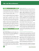
While this method is ideal for an exclusively PCI system, it does
pose problems for systems using both ISA and PCI, because PCI
BIOS cannot directly query ISA devices to determine which
resources they need. Using a PCI-ISA bridge (see diagram above)
to enable communication can help.
Another implication of the PCI implementation is that a board's
I/O address and interrupt are not fixed, meaning that they can
change every time the system boots. Consequently, application
software written for ISA boards, which are hard-wired to particular
interrupts, will not directly transfer to PCI-based systems. This is
a serious consideration when contemplating switching to PCI.
The High Speed, Wide Bandwidth Advantage
More than any other bus, PCI can take full advantage of today's
high-power microprocessors to deliver extremely high speed data
transfers. The original PCI bus was designed to operate with a
33MHz clock, to provide data transfer speeds up to 132 Mbytes/
sec. These 32-bit adapters can use multiplexing to achieve 64-
bit data transfers. (Later versions of PCI enable true 64-bit data
transfers using up to a 133MHz clock to enable transfer speeds
of up to 1066 Mbytes/sec.) These boards use a longer connector
that adds an additional 32-bits of data signals. This is done by
using the same set of pins to address and send data, the former
implemented on the first clock cycle and the latter on the second.
PCI's burst mode facilitates this operation as it allows a single
address cycle to be followed by multiple data cycles. A special
bus signal called a Cycle Frame is used to signal the beginning
and end of a transfer cycle. Parity signals are used to ensure
signal integrity, which is particularly vulnerable in such a complex
transfer system.
PCI Bus 7
PCI Bus 6
PCI Bus 5
PCI Bus 4
PCI Bus 0
PCI Bus 3
PCI Bus 2
PCI Bus 1
PCI-to-PCI bridge
PCI-to-PCI bridge
PCI-to-PCI bridge
PCI-to-PCI bridge
PCI-to-PCI bridge
PCI-to-PCI bridge
PCI-to-PCI bridge
ISA Slot
ISA Slot
ISA Slot
PCI-ISA
Bridge
PCI Bus 0
North-Bridge
DRAM
SRAM
CPU
(PCI Bus System with 8 PCI Busses and a PCI-ISA Bridge)
PCI