
Specifications


1.800.553.1170
Communication Overview
29
COM
The previous sections have discussed ways in which data is
transmitted and received. However, we have yet to discuss what
happens to the data between Point A and Point B. This in-
between area is a cable made up of wires through which data
travels. Specifications for this cable were developed to maximize
signal integrity (to limit the possible degradation that could be
caused by external noise or ground shifts). There are three main
methods for asynchronous and synchronous communication: RS-
232, RS-422 and RS-485. Differences between the three are
highlighted in the chart below and in the descriptions which
follow. The other option is parallel communication, which is
described on page 32. As noted earlier, when using USB, IEEE
1394, or any of the wireless interfaces, cabling is part of the bus
specification.
RS-232
The First Standard
RS-232 was introduced in 1960, and is currently the most widely
used communication protocol. It is simple, inexpensive to
implement, and though relatively slow, it is more than adequate
for most simple serial communication devices such as keyboards
and mice. RS-232 is a single-ended data transmission system,
which means that it uses a single wire for data transmission.
(Since useful communication is generally two way, a two-wire
system is employed, one to transmit and one to receive.) Signals
are processed by determining whether they are positive or negative
when compared with a ground. Because signals traveling this
single wire are vulnerable to degradation, RS-232 systems are
recommended for communication over short distances (up to 50
feet) and at relatively slow data rates (up to 20 kbps). However,
in practice, these limits can be exceeded.
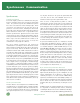
RS-232 RS-422 RS-485
Mode of Operation
Single-ended Differential Differential
Drivers per Line
1132
Receivers per Line
11032
Maximum Cable Length
50 feet 4000 feet 4000 feet
Maximum Data Rate
20 kbps 10 Mbps 10 Mbps
Driver Output Maximum Voltage
±25V -0.25V to +6V -7V to +12V
Driver Output Signal Level (loaded)
±5V ±2V ±1.5V
Driver Output Signal Level (unloaded)
±15V ±5V ±5V
Driver Load Impedance
3k to 7k 100k 54k
Maximum Driver Output Current (Power On)
n/a n/a ±100µA
Maximum Driver Output Current (Power Off)
V
MAX
/300 ±100µA ±100µA
Slew Rate
30Vµs max. n/a n/a
Receiver Input Voltage Range
±15V -7V to +7V -7V to +12V
Receiver Input Sensitivity
±3V ±200mV ±200mV
Receiver Input Resistance
3k to 7k 4k min. 12k min.
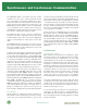
Data
Data
Transmitter
(Unbalanced, Single-wire Transmission)
Signal
Ground Return
DTE and DCE: Serial Communication Partners
A typical system is made up of two types of device, data
communication equipment (DCE) and data terminal equipment
(DTE). Typically DTE is defined as the communication source,
and DCE is defined as the device that provides a communication
channel between two DTE-type devices. For example, the diagram
on page 25 shows two modems (DCE) providing the
communication channel between a PC and a mainframe, two
DTE devices.
Data
Data
Transmitter
(Unbalanced, Two-wire Transmission)
Signal
Data
Data