
Specifications


1.800.553.1170
Communication Overview
25
COM
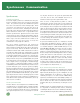
To combat this timing problem, asynchronous communication
requires additional bits to be added around actual data in order
to maintain signal integrity. Asynchronously transmitted data is
preceded with a
start bit
which indicates to the receiver that a
word (a chunk of data broken up into individual bits) is about to
begin. To avoid confusion with other bits, the
start bit
is twice
the size of any other bit in the transmission. The end of a word
is followed by a
stop bit
, which tells the receiver that the word
has come to an end, that it should begin looking for the next
start bit
, and that any bits it receives before getting the
start bit
should be ignored. To ensure data integrity, a
parity bit
is often
added between the last bit of data and the
stop bit
. The
parity
bit
makes sure that the data received is composed of the same
number of bits in the same order in which they were sent. See
the diagram (above right) for a portrayal of how asynchronous
communication works.
Incoming
Data
Sample
Strobe
Output
1
0
011010110
S
T
O
P
S
T
A
R
T
12345678
Incoming
Data
Sample
Strobe
Output
1
0
0110 0110
S
T
O
P
S
T
A
R
T
12345678
a. Best case, receiver samples at mid-point of each bit
b. Receiving clock is too slow, causing bit 4 to be skipped
and the data to be corrupted
(Ideal and corrupted asynchronous data sampling)
Asynchronous
The Simple, Inexpensive Choice
Most PC serial devices such as mice, keyboards and modems are
asynchronous. Asynchronous communication requires nothing
more than a transmitter, a receiver and a wire. It is thus the
simplest of serial communication protocols, and the least
expensive to implement. As the name implies, asynchronous
communication is performed between two (or more) devices which
operate on independent clocks. Therefore, even if the two clocks
agree for a time, there is no guarantee that they will continue to
agree over extended periods, and thus there is no guarantee that
when point A begins transmitting, point B will begin receiving,
or that Point B will continue to sample at the rate Point A
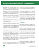
transmits. See the diagram below for an illustration of what
happens when transmission clocks differ significantly.
(Asynchronous Serial Communication System Model)
Upgraded UARTs For Increased Performance
At the heart of every asynchronous serial system is the
Universal Asynchronous Receiver/Transmitter or UART. The UART
is responsible for implementing the asynchronous communication
process described above as both a transmitter and a receiver
(both encoding and decoding data frames). The UART not only
controls the transfer of data, but the speed at which
communication takes place. However, the first UARTs could only
handle one byte of information at a time, which meant that the
computer needed to immediately process any transmission or
risk losing data as the next byte of information pushed its way
onto the UART. Not only does this makes for unreliable and slow
communication, it can slow down the entire system.
Improved UARTs, such as the 16750 UARTs, increase
communication speed and lower system overhead by offering
64-byte FIFOs (first in first out buffers). With the 64-byte FIFO
buffer, the UART can store enough information that the data
stream need not be suspended while the computer is busy. This
is particularly helpful in heavy multi-tasking operating systems
such as Windows 95/98/Me/NT/2000 and OS/2.
Enhanced Serial Adapters for Even More Speed
Even with 16750 UARTs, serial boards with a standard 1.8432
MHz clock can only reach speeds of 115.2 kbits/sec. This is
because the UART sets the baud rate by dividing down the clock
frequency, and the lower the clock speed, the lower the possible
data rate. The standard clock on Quatech serial boards can be
multiplied by a factor of one, two, four, or eight by using jumper
or software controls. High baud rates, up to 921.6 kbits/sec, can
be produced through a combination of changing the clock rate
multiplier and the UART baud rate divisor.