DSCLP/SSCLP-100 Two Channel Low Profile RS-232 Asynchronous Communications Adapter for PCI bus User's Manual QUATECH, INC. 5675 Hudson Industrial Parkway Hudson, Ohio 44236 1 TEL: (330) 655-9000 FAX: (330) 655-9010 http://www.quatech.
WARRANTY INFORMATION Quatech, Inc. warrants the DSCLP-100 or SSCLP-100 to be free of defects for five (5) years from the date of purchase. Quatech, Inc. will repair or replace any board that fails to perform under normal operating conditions and in accordance with the procedures outlined in this document during the warranty period. Any damage that results from improper installation, operation, or general misuse voids all warranty rights.
2006, Quatech, Inc. NOTICE The information contained in this document cannot be reproduced in any form without the written consent of Quatech, Inc. Likewise, any software programs that might accompany this document can be used only in accordance with any license agreement(s) between the purchaser and Quatech, Inc. Quatech, Inc. reserves the right to change this documentation or the product to which it refers at any time and without notice.
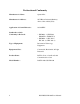
Declaration of Conformity Manufacturer's Name: Quatech Inc.
Table of Contents 1 General Information . . . . . . . . . . . . . . . . . . . . . . . . . . . . . . 2 Hardware Configuration . . . . . . . . . . . . . . . . . . . . . . . . . 8 9 2.1 Factory Default Configuration . . . . . . . . . . . . . . . . . . . . . . . 9 2.2 Enable Scratchpad Register (SPAD, J2) . . . . . . . . . . . . . . 9 2.3 Force High-Speed UART Clock (X2 or X4, J4-J5) . . . . 10 3 Hardware Installation . . . . . . . . . . . . . . . . . . . . . . . . . . .
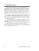
1 General Information The Quatech, Inc. DSCLP-100 (two-port) and SSCLP-100 (one-port) provide RS-232 asynchronous serial communication interfaces for Low Profile IBM-compatible personal computer systems using the PCI expansion bus. The DSCLP-100 uses Quatech's new Enhanced Serial Adapter design. Legacy serial port data rates are limited to a maximum of 115,200 bits per second. This manual usually refers to the DSCLP-100.
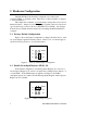
2 Hardware Configuration The DSCLP-100 is automatically configured at boot time by the computer's BIOS or operating system. There are no required switches or jumpers to set for installation. This chapter lists a number of optional jumper settings that control various hardware features. Jumpers J2, J4-J5 are grouped together at the end of the board opposite the D-type connector (D-25 for DSCLP, D-9 for SSCLP).
2.3 Force High-Speed UART Clock (X2 or X4, J4-J5) These jumpers force an increase of the UART input clock frequency by a factor of two or four. This feature can allow legacy software to use baud rates above 115,200 bits per second. It is also useful if the serial port device driver does not directly support setting the higher baud rates through the Options Register (see section 4.4).
3 Hardware Installation 1. Turn off the power of the computer system in which the DSCLP-100 is to be installed. 2. Remove the system cover according to the instructions provided by the computer manufacturer. 3. Make any desired optional jumper setting changes. 4. Install the DSCLP-100 in any empty PCI expansion slot. The board should be secured by installing the Option Retaining Bracket (ORB) screw. 5. Replace the system cover according to the instructions provided by the computer manufacturer. 6.
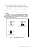
4 Address Map and Special Registers This chapter explains how the two UARTs and special registers are addressed, as well as the layout of those registers. This material will be of interest to programmers writing driver software for the DSCLP-100. 4.1 Base Address and Interrupt Level (IRQ) The base address and IRQ used by the DSCLP-100 are determined by the BIOS or operating system. Each serial port uses 8 consecutive I/O locations.
4.2 Enabling the Special Registers The DSCLP-100 contains two unique registers, an Interrupt Status Register and an Options Register. These registers are enabled when the SPAD jumper (J2) is removed (factory default). They replace the UART Scratchpad Register on accesses to register address 7. The Interrupt Status Register and Options Register are accessed through the scratchpad location of any UART. The DLAB bit of the UART (Line Control Register, bit 7) is used to select between the two registers.
4.4 Options Register The Options Register allows software to identify the DSCLP-100 as a Quatech Enhanced Serial Adapter. It also allows software to set the UART clock rate multiplier. Figure 9 shows the structure of the Options Register. The powerup default of the Options Register is all bits zero.
4.4.2 Clock Rate Multiplier A standard RS-232 serial port operates at a clock speed of 1.8432 MHz. In order to achieve higher data rates, Quatech Enhanced Serial Adapters can operate at two times, four times or even eight times this standard clock speed. This is controlled by the clock rate multiplier bits in the Options Register. Software can determine the UART clock frequency by reading the clock rate multiplier bits RR1 and RR0 in the Options Register as shown in Figure 11.
5 Windows Configurations 5.1 Windows Millennium 1. After inserting the DSCLP-100 for the first time the "Add New Hardware Wizard" will begin. Select "Search for the best driver for your device.". Check the "Removable media" and "Specify location" box. Click the "Next" button. 2. Window will locate the proper INF file and copy the file from the CD. Click the "Next" button. 3. The final dialog screen will verify the file copy from the CD. Click the "Finish" button.
5.2 Windows 2000 1. After inserting a DSCLP-100 for the first time, the "Add New Hardware Wizard will appear at start up. Click the "OK" button. 2. The following dialog box will be displayed. Insert the Quatech COM CD (shipped with the device). Click the "OK" button. 3. The following dialog box will display the appropriate INF file on the CD in the drive. Click the "OK" button. 4. Window will copy the INF file from the CD and display a final dialog indication that the process is complete.
5.3 Windows 98 1. After inserting a DSCLP-100 for the first time, the "Add New Hardware Wizard will appear at start up. Click the "Next" button. 2. Select "Search for the best driver for your device". Click the "Next" button. 3. 16 On the next dialog, select the "CD-ROM DRIVE" check box. Insert the Quatech COM CD (shipped with the device) into the CD-ROM drive. Click the "Next" button.
4. The following dialog box will display the appropriate INF file on the disk in the drive. Click the "Next" button. 5. Window will copy the INF file from the disk and display a final dialog indication that the process is complete. Click the "Finish" button. 5.4 Windows 95 Windows 95 maintains a registry of all known hardware installed in your computer. Inside this hardware registry Windows 95 keeps track of all of your system resources, such as I/O locations, IRQ levels, and DMA channels.
5.5 Using the "New Hardware Found" Wizard The following instructions provide step-by-step instructions on installing the DSCLP-100 in Windows 95 using the "New Hardware Found" wizard. 1. After booting the computer with a newly-installed DSCLP-100, the "New Hardware Found" dialog box will appear. If you have never installed a Quatech PCI communications adapter before, the dialog box may simply indicate that it has found a "PCI Card." 2.
NOTE: You may be able to skip this step if you are certain that your system has the latest version of these files installed. If you do not have your Windows 95 install disks immediately available, click "OK" anyway. A dialog box appears with an option to Skip the files. Click the Skip button and the files will not be installed. This is all right if the latest version of these drivers are currently in the \WINDOWS\SYSTEM directory. 9.
5.6 Viewing Resources with Device Manager This discussion applies equally to Windows 95/98/ME and 2000/XP. The following instructions provide step-by-step instructions on viewing resources used by the DSCLP-100 in Windows using the "Device Manager" utility. Select Start|Help from within Windows for additional information on this utility. 1. Double click the "System" icon inside the Control Panel folder. This opens up the System Properties box. 2.
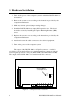
Figure 12--- Windows Device Manager 6. The DSCLP-100 serial ports are also listed under the group Ports (COM and LPT). Windows 95 does not assign COM1-COM4 to ports addressed at nonstandard locations. The DSCLP-100 ports will be enumerated starting with COM5 (or higher) even if lower logical numbers are available. 7. Select any of the Quatech Serial Ports listed under the group Port (COM and LPT) and click the "Properties" button.
Figure 13 --- Windows Device Manager 9. Use the Logical COM Port names to access the serial ports on your DSCLP-100 through your software applications. Note: The Logical COM Port name is assigned to your ports by Windows . This name is required by a Windows application when accessing a particular port.
5.6.1 Changing Resource Settings with Device Manager 1. Start the Windows 95/98/ME Device Manager. 2. Double click on the hardware class Multi-Port Serial Adapters to list hardware devices in the class. 3. The DSCLP-100 “parent device” belongs to this hardware class. The full device name for the DSCLP-100 is Quatech DSCLP-100: Dual-Port RS-232 Serial Adapter.
4. Open the Properties dialog for the DSCLP-100 device, then click the Resources tab to view the Input/Output Range and Interrupt Request resource allocations. Do not change these settings without specific instructions from a Quatech Technical Support Specialist. To exit without saving changes, click the “cancel” button. 5. Open the Properties dialog for the DSCLP-100 device, then click the Advanced tab to view the clock rate settings.
Clock Mode Auto X1 X2 25 Data Rate Multiplier Max bps Description Auto clock mode enables applications to request any baud rate up to 921,600. 921,600 The hardware drivers will select the correct clock multiplier based on the baud rate requested The X1 clock mode mimics a standard COM port. The hardware drivers lock 115,200 the clock to the standard rate. The port will run at the baud rate requested by the application.
X4 460,800 X8 921,600 for legacy applicattions which cannot request baud rates over 115,200 The X4 clock mode locks the ports hardware clock at four times the standard rate. The baud rate the port runs at will always be four times the rate requested by the application. This mode is useful for legacy applications which cannot request baud rates over 115.200. The X8 clock mode locks the ports hardware clock at eight times the standard rate.
8. Click the "Port Settings" tab and then click the "Advanced" button. The DSCLP-100 driver will display a custom Advanced Port Settings control, which allows the ports UART compatibility mode and FIFO threshold levels to be configured. The threshold values of full-scale for the transmit buffer and ¾-scale for the receive buffer are optimal for most applications. Note that the FIFO option for each of the DSCLP-100's ports is configured independently.
DSCLP/SSCLP-100 User's Manual
6 Other Operating Systems Device drivers for Windows NT and OS/2 are also available for the DSCLP-100. The board can be used under DOS and other operating systems as well in many circumstances. The software described below can be downloaded from the Quatech web site if it did not come with the board. 6.1 Windows NT The Windows NT device driver is installed by running the SETUP program. Up to 256 serial ports are supported.
6.3.1 QTPCI.EXE Quatech's "QTPCI" utility supplies the information required when modifying the serial port settings of the application. This program should be run from real DOS, not in a Windows DOS box. Figure 14 shows the Basic Mode display for the DSCLP-100 after the "Q" key has been pressed. In this example, the DSCLP-100 uses I/O base address FF80 hex and IRQ 11. The hardware revision of the DSCLP-100 is also displayed.
Figure 15 shows the Expert Mode display for the DSCLP-100 after the "Q" key has been pressed. The information from the Basic Mode display is presented along with more details such as the Vendor and Device IDs, PCI Class Code, size of memory and I/O regions, etc. Pressing the "N" key will show similar information for all non-Quatech PCI devices in the system, including those devices integrated on the motherboard. In this example, the "Base addr 0" resource is reserved.
7 External Connections RS-232-C devices are classified by their function as either Data Terminal Equipment (DTE) or Data Communication Equipment (DCE). Generally, data terminal equipment is defined as the communication source and data communication equipment is defined as the device that provides a communication channel between two DTE-type devices.
The DSCLP-100 is a DTE device which connects to peripheral equipment through a single male D-25 connector, or using the adapter cable, two male D-9 connectors. The standard serial port connections are listed in Figure 18.
8 PCI Resource Map Listed below are the PCI resources used by the DSCLP-100. Such information may be of use to customers writing their own device drivers or other custom software. A detailed description of the DSCLP-100's UARTs is available on the Quatech web site. (all numbers in hex) PCI Vendor ID: 0x135C Quatech, Inc.
9 Specifications Bus interface: PCI, 32-bit bus, Universal Voltage Signaling IBM-compatible computers Dimensions: approx. 5.0" x 3.7" Serial ports Controller: 16550 with 16-byte FIFOs Interface: Transceivers: DSCLP: One male D-25 connector (Two male D-9 connectors using adapter cable.) SSCLP: one male D-9 connector. ICL3245CA High-level output: Low-level output: Switching speed +5V min -5V max, Power requirements +5.0 volts: approx.
Data Rate (kbaud) 921.6 460.8 230.4 115.2 4% trans time N/A 100 330 800 Maximum Load (pF) 10% 15% 20% trans trans trans time time time 100 300 430 430 670 900 900 1100 1630 1570 3300 4300 25% trans time 470 1100 2000 4800 Note 1: The signal transition time ratio is defined as the percentage of the unit interval or bit time (the inverse of the data rate) that is occupied by the signal transitioning from -3V to +3V.
10 Troubleshooting Listed here are some common problems and frequent causes of those problems. If the information here does not provide a solution, contact Quatech technical support. Any unauthorized repairs or modifications will void the DSCLP-100's warranty. Computer will not boot up. 1. Is the DSCLP-100 properly inserted? Remove the card and try again. Perhaps try a different expansion slot. 2. Ensure that an ISA-bus card is not using the same IRQ that the PCI BIOS tries to assign to the DSCLP-100.
DSCLP/SSCLP-100 User's Manual Revision 1.