
User`s manual


Eagle 2000 – 2kW FM Broadcasting Amplifier
User’s manual – Page 14 of 66
5 CIRCUITS DESCRIPTION
, This section’s sole purpose is to provide general explanations about the device operation in order to simplify the
maintenance by skilled personnel appointed by Quark. As already mentioned, no internal adjustments are required for
normal operation. Tampering with the internal settings makes the warranty null and void. Moreover, could seriously
damage the equipment, compromising the guaranteed performance.
, Several modules are highly specialized and difficult to repair even by skilled technicians and must therefore be
replaced with new modules, and, if possible, sent to the manufacturer in order to verify the possibility of a repair.
, Any inspection of the described modules must be carried out with the cover removed and, in many cases, with the
equipment connected to the power line. Although some live parts are insulated and difficult to reach, this involves the
risk of accidental contact with the power line voltage. In order to avoid this, use only insulated tools and never touch
the main power supply switch or the power sockets when the equipment is connected to the power line.
, Do not operate the equipment without the covers properly screwed on. If the top cover is removed, malfunctioning of
the equipment may occur, as well as of any other electronic measuring instrument, owing to the strong R.F. fields
involved.
Eagle 2000 is composed of the following elements:
• Power supply unit
• R.F. amplifier section
• Control board
• Analog board
• Fans control board
• LCD display and control panel button board
• Digital encoder
5.1 Power supply unit
The Power supply unit is an αPower AC/DC converter (3kW and 48V
DC
rating) with PFC (power factor correction) with output
voltage adjustable from 0 to 30V
DC
. This supply voltage is adjusted according to a 0-12V command signal sent by the analog board
via a flat cable. The unit produces two supply voltages: a 30-48 V
DC
to supply the R.F. amplifier unit, and a 15V
DC
to supply the
service boards (excluding the control board which is powered by the 48 V
DC
).
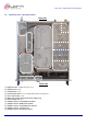
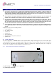
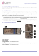
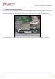
5.1.a Power supply unit connections and indications
[31] Mains voltage - coming from the power supply relay.
[32] Power Supply status LEDs.
31
32