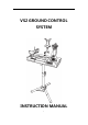
VS2 GROUND CONTROL SYSTEM INSTRUCTION MANUAL 1
TABLE OF CONTENTS 1. Introduction.............................................................................................................4 2. OverallLayoutofGroundStation....................................................................5 2.1Exterior&Interface.......................................................................................5 2.2Training,Simulation,UHFport.................................................................6 2.3BatteryandCharger........
5.5LinearCurveSetting...................................................................................18 5.6MixingSetting...............................................................................................19 5.7ReceiverLinkProcedure............................................................................20 5.8FailSafeSetting............................................................................................20 5.9ButtonMonitor.................................
1. Introduction ThankyouforpurchasingaVS2GCSseriesdigitalproportionalR/C system.Thissystemisextremelyversatileandmaybeusedbybeginners andprosalike.Inorderforyoutomakethebestuseofyoursystemand toflysafely,pleasereadthismanualcarefully.Duetounforeseen changesinproductionprocedures,theinformationcontainedinthis manualissubjecttochangewithoutnotice.
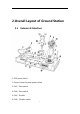
2. Overall Layout of Ground Station 2.1 Exterior & Interface 1. GCSpowerswitch 2. Groundcontrolsystempowerswitch 3. CH5/Twistswitch 4. CH6/Twistswitch 5. CH3/Throttle 6.
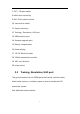
7. CH7/3Gradesswitch 8. Multi-rotorunlockkey 9. Roll/Pitchmintrimswitch 10. Yawmintrimswitch 11. Systemmenukey 12. Training/Simulation/UHFport 13. USBextensionport 14. firmwareupgradeport 15. Batterycompartments 16. Powerdisplay 17. 12VDCElectricaloutlet 18. 2.4GHztransmissionmodule 19. 360°non-direction 20. screenstand 2.
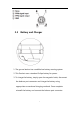
2.3 Battery and Charger 1.Thegroundstationhasaaudiblelowbatterywarningsystem. 2.ThisProductusesastandard3slipobatteryforpower. 3.Tochargethebattery,simplyopenthemagnetichatch,disconnect thebalanceportconnectorandchargethebatteryusing appropriateconventionalchargingmethods.Oncecomplete reinstallthebatteryandconnectthebalanceportconnector.
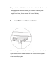
4.Thisproducthasa12VDCelectricaloutletontheback.Canbeused tosupplypowertothescreen.Ifyouinsertanexternalpower supplyfromhere,pleaseremovetheinternalbattery. 2.4 Installation and transportation Removethegroundstationfromthetransportcaseandusethe4 quickreleasethumbscrewstoattachtheconsoletothetripodor othermountingsystem.
2.5 Packing list 1.GroundcontrolsystemVS2controlpanel 2.Screenstand 3.Tripod,fastrelease&clip-onscrewsfortripod 4.Hexagonwrench,sparescrew 5.FirmwareupgradeUSBcable 6.
3. Basic Operation 3.1 Insert New Joystick WhenthesystemdetectednewUSBjoystick,itwillaskwhetherto activatethenewjoystick.Iftheanswerisyes,thesystemwillclear currentconfigurationandacceptthenewlyinsertedjoystickas primarydevice. 3.
Duringtheinitiationofthesystem,ifthethrottleisnotatthelowest position,thesystemwillalarm,andsuspenduntiltheuseradjustthe throttletothelowestposition.Iftheuserclicked“CloseRF”,theRF systemwillbeshutdowntoprotecttheuserwhenthesystemis initiated. 3.3 Default setting of Joystick 1. CH6/Twistswitch 2. CH5/Twistswitch 3. Throttle 4. Aileron 5.
6. Elevator 7. CH8/3Gradesswitch 8. Roll/Pitchmintrimswitch 9. Multi-rotorunlockkey 10. Yawmintrimswitch 11. CH7/3Gradesswitch 12. Systemmenukey 4. Instruction of Menu Operation 4.1 WINDBOX Buttons for Menu Operation Press“MenuRightButton”toentermainmenuwhenunderthe systemhomescreen.
4.2 System Home Screen A.Atimerisontheleftoftheinformationbar B.InsertedUSBjoystickstatusisinthemiddleoftheinformationbar C.Thebatteryvoltageisontherightoftheinformationbar D.
4.3 Sub-menu Operations Forenteringsub-menu,press“MenuRightButton”whenundermain menu. Sub-menuOperation A.Back:press“MenuLeftButton”toreturntoupperlevelmenu.Press “MenuUp”and“MenuDown”buttonstoselectsub-menu. B.Menuwithoutoptions:press“MenuLeftButton”toreturntoupper levelmenu.Press“MenuRightButton”toentersub-menu. C.Menuwithoptions:press“MenuLeft”and“MenuRight”button tosettheparameters.
D.Theuparrowattheuprightcornerofthemenuscreenindicates previouspageavailable. E.Thedownarrowatthedownrightcornerofthemenuscreenindicates nextpageavailable. 5. Functions 5.1 Servo Monitor Thisfunctioncanbeusedtomonitorthevaluesofallchannels.Thefirst pageshowsthevaluesofthefirsteightchannels;press“MenuDown Button”tomovetonextpageforthevaluesofothereightchannels. Press“MenuLeftButton”toreturntoupperlevelmenu.
5.2 Trim Setting ●Optionone:selecttargetedchannel ●Optiontwo:thevalueoftrim ●Optionthree:Resettrim.sub-trimisresettotheinitialvalue. 5.3 D/R Setting Thisfunctioncanbeusedtoadjusttheoutputrangeofthechannel. ●Optionone:disableorenableallchannelsdualratefunctions. ●Optiontwo:choosetargetedchannel.
●Optionthree:changetheratevalueofthetargetedchannel.The defaultvalueis100%;adjustablerangefrom50%to150%. 5.4 CH Reverse Setting Thisfunctionreversestheoperationdirectionofthesticks,switches, trimmerlevers,andknobs ● Optionone:choosetargetedchannel ● Optiontwo: "NORM":Normaloperationdirection "Reverse": Operationdirectionisreversed.
5.5 Linear Curve Setting Thisfunctioncanbeusedtoadjustthelinearcurveofspecificchannels. ●Optionone:enableordisablethecurvefunctionsofallchannels ●Optiontwo:choosethetargetedchannel ●Optionthree:selectthepointforformingthecurve(Atotalof5points) ●Optionfour:thevalueofselectedpointinx-coordinate ●Optionfive:thevalueofselectedpointiny-coordinate Therevisedcurvecanbepreviewed. Note: 1.
2.Thex-valueofcurrentpointshouldbelargerthanthex-valueof previouspoint,andsmallerthanthex-valueofnextpoint. 5.
FormixingofacarcontrolleroraUSBsteeringwheel,throttleandbrakepedal shouldbemixedtoamainchannel. 5.7 Receiver Link Procedure Pleaserefertotheexternaltransmitterandreceiverinstructionsyou purchased. 5.8 Fail Safe Setting Pleaserefertotheexternaltransmitterandreceiverinstructionsyou purchased. 5.9 Button Monitor Onthebuttonmonitorscreen,whenpressanybutton,corresponding numberonthescreenwillflash.
buttoncanbeconfirmed.Suchnumberwillbeusedinbutton mappingwhichwewillexplaininnextchapter. 5.10 Button Mapping WINDBOXcanmapanybuttonofthejoysticktoaspecificaction.For instance,a3-segmentswitch,shortcutforunlockmulti-rotorscraft, trimbutton,andsoon.
z Close:donotmapthecurrentbutton z High:Setchannelasathree-stageswitchandsetittohigh z Middle:Setchannelasathree-stageswitchandsetittomiddle z Low:Setchannelasathree-stageswitchandsetittoLow z Three-stageSwitch:Setchannelasathree-stageswitch,switchthethreestage byorder. z Two-stageSwitch:Setchannelasatwo-stageswitch,switchthetwostageby order. z Thechannelvalue+:Pressthebutton,thechannelvalueisincreased.
z UnlockShortcut:triggerunlockactionofmulti-rotorcraft z APM1-6:trigger segmentofsix-segmentAPMswitch Note: Ifthechannelwasalreadymappedtojoysticklinearaxis,it’sa musttocancelmappingfirst,otherwise,therewillbeconflict.Theway ofcancelingmappingisreferredtothechapter“CancelMappingto Joysticklinearaxis”. Example1:IfwewanttomapthebuttonofSaitekX52ProJoysticktothe 3-segmentswitchofCH8, 1.
6. Refertostep1tofindthebuttonnumberforthethirdbuttonofthe joystick,i.e.,28.SelectCH8foroption2;select“Low”foroption3. Thenthethreebuttonsaremappedtothe3-segmentswitchinCH8. Example2:thewaytomapthePOVhatbuttonofthejoysticktothe menubuttonoftheWINDBOXisasfollows(basedonSaitekX52) 1. Firstlyopen“ButtonMonitor”,findthenumberofthePoVhat; 2.
5.11 Cancel Button Mapping Sometimes,weneedtoreleaseonechannelforlinearaxisofthejoystick. Then,wehavetocheckwhetherthechannelismappedtocertain button. Forexample:forcancelingthemappingbetweenthebuttonofSaitek X52andCH8, 1. Open“ButtonMapping”menu.Selectbutton30foroption1,and CH8foroption2; 2. Select“Close”foroption3; 3. Refertostep1,settheactionofButton28and29as“Close”; 4. ThenthemappingbetweenbuttonsandCH8iscanceled.
●Option1:recordthespecificactionsofunlocking; ●Option2:setholdtimeofunlockingaction. Thewaytorecordspecificunlockingaction: 1.Selectoption1andthenpressrightbuttontorecordtheunlocking action; 2.Keepthejoystickatunlockingpositionspecifiedbyflycontroller,and keepsuchposition; 3.Selectoption1andthenpresspressleftbuttontostoprecording. Note:Pleasekeeptheunlockingpositionuntiltheendofthe recording.
3.Select“Button2”foroption1. Ignoreoptions2. 4.Select“Unlock”foroption3.Thenthesettingforunlockingshortcut iscompleted.Pressbutton2candirectlyunlockthemulti-rotorcraft. Attentions:pressingunlockingshortcutisequaltoconductunlocking action,themotorwillrunwithidlingspeed.Pleasebecareful.It’s bettertoselectabuttonwithcoverasshortcut,forexample,thefire buttonofX52. 5.
Thewaytomapbuttonstoeachsegmentofasix-segmentswitch: 1.Open“ButtonMonitor”,pressspecificbuttonofthejoystick,and confirmedthenumberofthatbutton(assumedasbutton2); 2.Open“ButtonMapping”menu; 3.Select“Button2”foroption1,andselecttheplannedmapping channelforoption2; 4.Select“APM1”foroption3; 5.Refertoabovestepstosetotherfivesegmentsoftheswitch. 5.
●Option1:joystickdisplaymenu.Clickittoentersub-menutoviewthe axisnamesofthejoystick; ●Option2:selectthenameoftargetedaxisoftheUSBjoystick; ●Option3:selectthechannelnumbertobemappedtothetargeted axis. Forexample:formappingtheleftandrightdirectionaxisofjoystick tochannel1, 1.Clickoption1toenterjoystickdisplaysub-menu.
Thewaytocancelthemappingforaxisofthejoystickisasfollows: (assumption:cancelthemappingbetweenRXaxisandCH6) z Select“RX”foroption2 z Select“CH13”foroption3(i.e.,themaximumchannelnumber +1). 5.16 Trainer Setting TheTrainerfunctionmakesitpossiblefortheinstructortochoosewhich channelsaretobeusedforinstruction,makingitpossibletomatchthe trainingabilitytothestudent'sskilllevel.
●Option1:TrainerswitchON/OFF.Abuttonofthejoystickcanalsobe mappedtoaswitchtoenableanddisablesuchfunction. ●Option2:selectthetargetedchannelfortheTrainer. ●Option3:selectsourcechannel. ●Option4:selectthedatasource:Joystick,PPMIN. Forexample,forusingaWINDBOXasTrainer,thesettingisasfollowing: 1.
4.TurnonTrainerfunction,shakethejoystickofthetrainee.Inthe channeldisplaymenu,youcantracetheactionofthetrainee. Forexample,howtomappingthechannelofthetraineecontrollertothe specificchannelofcoachcontroller? Indefaultsituation,theCH1ofthetraineecontrollerwillbemapped totheCH1ofthecoachTransmitter,andtheCH2ofthetrainee TransmitterwillbemappedtotheCH2ofthecoachTransmitter,and theotherchannelsfollowthesamerule.
5.17 Connect with 433/915M Range Extender WINDBOXcanworkwith433/915Mrangeextendertoincrease remotecontroldistance.TheWINDBOXwilloutputPPMsignalstoa 433Mtransmittermodule,andtherewillbea433Mbpsreceiveron theaircraft. Settingwithcable: 1. Connecting:Onesideofthesimulatorcableshouldbeconnected tothePPMinputportofthe433Mrangeextender; 2. Theothersideofthesimulatorcableshouldbeconnectedtothe PPMoutputportofWINDBOX; 3.
5. Select“futabaPPM”foroption2. Ifthesimulatorcablewasmadebyusersthemselves,connectthetwo wiresoftheaudioplugwiththePPMconnectorofWINDBOX. Thesignalwireinthemiddleoftheaudioplugofthesimulatorcable <—>PPMpinofthePPMconnectorofWINDBOX Thegroundingwireattheedgeoftheaudioplugofthesimulator cable <—>GNDpinofthePPMconnectorofWINDBOX 5.19 Low Battery Alarm Setting z Option1:selectalarmvoltage.
z Option3:enableordisablelowbatteryalarmfunction. 5.20 Configuration Setting WINDBOXcansavefiveconfigurationformodelaircraftatmost. z Option1:toswitchtheconfigurations.(ifapplythenew configuration,pleasesavetheconfiguration,repoweronthe windbox) z Option2:savecurrentconfiguration. z Option3:resetcurrentconfiguration,alltheconfigurationswillbe cleared.Insertedjoystickwillberegardedasnewdevice.
Ingeneral,ifaconfigurationisrevised,thesystemwillautomaticallysave theconfigurationwhenthethrottleatthelowestposition.Sometimes, thereisa“beep”tonewhenthethrottleisatthelowestposition,that meansthesystemsavedtherevisedconfigurationautomatically. 5.21 Throttle Setting WhentheThrottleOfffunctionisenabled,thethrottleoutputwill alwaysatthelowest,nomatterwhat’sthepositionofthethrottleaxis ofthejoystick.