
User Manual
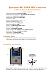
AV1, AV2 – AV outputs. Impedance – 75R, standard 1v p-p output. 3.5mm stereo audio
jack.
Power In – Power Jack 1.3X3.4mm. Supply voltage 6..18VDC
Navigation button – 5 position navigation button (Up/Dn/Left/Right/Enter) – main
control for choosing working mode, scanning frequencies, settings etc.
LED1 (Blue and Red) – Blue LED is indicating video signal presence. Red LED indicating
active receiver in Diversity mode.
LED2 (Blue and Red) – Blue LED is indicating video signal presence. Red LED indicating
active receiver in Diversity mode.
Operating modes:
Diversity mode – both receivers always have the same channel selected. Both AV
outputs OUT1 and OUT2 output signal from the receiver module which has better
reception. The MCU selects receiver module which will be used based on the sophisticated
algorithm using video signal recognition, RSSI and other factors.
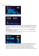
Independent mode – Each receiver module can be controlled independently via
navigation button and display. Each module outputs AV signal to its dedicated output
OUT1 and OUT2 respectively. Receiver works as two independent receivers with two
antennas and two independent outputs. Each module can be set on each own frequency.
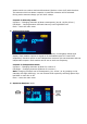
Spectrum Analyzer mode – Radio module 1 constantly sweeping channels and collects
data with dynamic indication data on the display and radio module 2 works as a video
receiver with video output to OUT1 and OUT2.
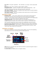
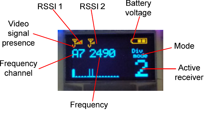
Indication on display:
When unit is powered on it enters Diversity mode by default. This is the main operating
mode. Below is the screen in Diversity mode right after power ON.
Note: Receiver remembers last used channel and when it is powered on again it stays on
the last used frequency.
To enter menu press ENTER (click on navigation button)