
User Manual

SIN
Q3-O
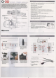
Function
1
1i1l motor connector(PIT)
connect WlIhlhe til! motor,
2
RoIling molor oonnector(ROLL)
Connect with the rol1ing motor.
3
Horizontal
motor connector(YAW) Connect with lhe horizontal motor.
4
Gyro connec\or(GYRO)
Connect with lhe
gyfO.
5
Sensor connector(SENCOR CON) Connect with lhe sensor.
6
Audioand
vkíeo
input
I
power output
Audio and video input
I
~..,er cutout.
.,
conoectcr (NV INlPOVVI::ROUTPIlT)
7 Operaling status
indicatcr
(GJR/B/Y)
Operating stat~.
il~ication
{green
J
red
I
blue
I
yellow light):
B
Function keys(FN) Function selectión keys when entering into adjustment modé,
9
Power input
I
data connector
power input DC 7.4V-28V (recommended 12V,35 lipo
baUery)
I
data connection.
10
Toggleswltch( ' •..•...•• 0)
Switch between stick position mode (position 1)
and rate mode (posüion
O).
11
ROLLKnol>
AUX contrai knob.
12
PITKnob
AUX control knob.
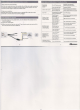
5.0 Instrudions for eonneeting without receiver
5.1 Control knob function
PIT control knob Adjusting lill angle(midpoinl is
O·,
angel range ís
-135·- 90°)
ROLL control knob
Adjusting roll angle(midpoinl is O·, angel range is -45·- 45·)
52
Adjusting
method
Place the 9imbal in a horizontal posilion, lhe gimbal will b.egin inilialization, lhe red LED will
nasn when inilialization nas finished, when lhe green LED remain solid, you can adjusl lhe Iilt
ano rolling angle according tothe gimbal
status. ~- -'
(i}
Ifyou ;"ant
to
position the Gimbal forward, adjust lhe PIT knob in a counterclockwise
oírecüon,
and vice versa.
I
(2) 11
you wanl to position lhe Gimballéft / righl, adjust the ROLL knob in a counler ciockwise
(\írec\ion, and vice versa.
6.2 Setting ~ethod
Place lhe gimbal in a horizontal posilion, once initialized lhe red LED will flash, once
initialization ís complete lhe green LED will remain solid, you can than adjust the tilt an,
angle according
10
your requiremenls. Take lhe mid-polnt as lhe start point, you can ad
the PIT knob in a counter clockwise direction as needed
10
seI lhe till range (rnaxímurr
-135· - 90·)
Adjust the ROLL knob to set lhe rolling rálge by following the same prece
( maximum -45. - 45·).
6,3 Instruction for stlck mode
(1) Stick position mode means you can adjusl lhe till and roll angle Ihrough your Iransn
till and roll stick. Turning switch
(1
+-Q)-+
o) to lhe 1 posilion, lhe till and
rolí
angle vvi
changed corresponding to the till and roll stick inpu1. The sticks mid posilion will be
start position, the greater the til! and roll input, lhe grealer lhe gimbal tilt and roll anf
be increased and vice versa. The gimbal lilt and roll angle vvill be
O·
when lhe till an
stíek
is aI lhe centre position.
(2) Slick rate mode means you can adjusl lhe lilt and roll rale Ihrough your transmitter I
roll stick. Tuming swilch(l~o) to O posilion, lhe til!
and
roll rale will be
changec
corresponding to lhe tilt and roll stick input, take lhe mid-position as lhe start positio
greater lhe tilt
ano
roll stick input, the greater lhe gimbal till and roll rale will be incrs
and vice versa. The gimbal till and roll rate will be O· when lhe tllt and roll stick is aI
cenlre position.
Aemark: When using the lransmitter contrai knob
10
adjust lhe gimbal
tilt
and
roll,
we
l
you adopl lhe position mode (
slide
the swilch
10 1
position), same as lhe transmitter
S'
6.0 Instructions for connecting with receiver
6.1 Control knob functions
PIT control knob
Adjusting tilt angle(maximum
-135'- 90·)
Adjusting roll angle(maximum -45°-45.)
ROLL control knob
·5·
$_
xx
7.0 Instructions for adjusting
parameter mode
7.1 Control knob functions
PITKnob
Adjusting motor gain co lIot
ROLLKnob
Adjusting motor output power.
7.2 Parametêr adjustment principIes
In the event thal the carnera needs
10
be cha.'lgeÕ [te a rem weight of camera), you wil1
be
recureo
to adjusllhe parameters
accord'
;g 10lhe Ioad cooditi:lns. Under lhe heavier
load conditions, when the motor output power íocrêases. )'OU
lIlIlSi
redoce the motor
control gain. When the motor outpu! decreases due io ~ Ioad;,; voo canappropriatety
increase the control gain. Therefore, when \l1e pawef is CCfieCI,. by iocreasing lhe molor
power, you can ootaín larger control gain and
ifTlproYe me
sIatlíiZa1ioo effed. When lhe
motor power is reduced, the gimbal's ability to
RSÍSt~
-00 reduced at lhe
samenme.
.., ,3 Adjustment methods
Place lhe gimbal in a horizontal position. Switchoo lhe powa-aiI.'ldtbe girnbal will enter into
the inilialization state. A red LED will flash iolloweà
by;2
greeo
l..ED~
will become solid
alter lhe red LED ceases to flash. Under Ihis condiIion. )'OU caQ
e:néaf"!De
reference model
to adjust lhe gimbal parameters when necessary,
7,3.1
Entering Into PAM instructions
Press function key (FN) for 3 seconds, RedJBlueIYelIIow
indicatinq PAM entered.
7.3.2 Tilt motor output power and gain control
adjustmen{
(1) Enlering into lhe PAM settings, press lhe function key. _ !fie fed lED flashes
QUickly indicaling til! motor output power ano gain
()(Jfl3d~
5llOde
ís. entered_
(2) Resel lhe PIT/ROLL control knob which denotes -
m
J....
must be aI the
center positíon, the blue/yellow LED vvill remai so&i
(3)
Wail
3-5
seconds until the red LED flashes s!owIy,)'OU G3ft adjustlbe motor
output power and gain control. 1 To increase lhe l1ft
fIlEÉIf ~
lhe ROLL
knob clockwise and lhe yellow LED wiJI flash and \ÃCe-ws:sa.2l&iJcteese li!. motor
gain, adjusl lhe PIT control knob ciockwise and lhe biue l..ffi
êi9f!
'fice verna.
-6·
simuitaneously
(4) Press funclion key (FN) 3 times until lhe green LED remains solid, lhe adjusted
parameters will be saved and the system will exit lhe PAM settings.
c
7.3,3
RolI motor output power and gain control adjustment
(1) Enter ínto lhe fiAM settings, press the function key(FN) twice until lhe blue LED fia
quickly indicating roll motor outpul power and gain control adjusting mode is enters
(2) Resel lhe PrT/ROLL control knob which denotes PIT/ROLL conlrol knob is ai lhe c
position, lhe redJyellow LED remains solid
(3) Wail
3-5
seconds until the blue LED flashes slowly, Ihen you can adjust lhe RolI m
output power and gain control. <DTo increase lhe RolI motor OUlput power, adjust I
ROLL control knob clockwise and lhe yellow LED wil1 flash, and vice versa.@To
increase lhe RolI molar gain, adjust lhe PIT conlrol knob clockwise and lhe red LEI
flash and vice versa.
(4) Press iunclion key (FN) lwice until the Green LED remains solid, the adjusled para
will be saved and lhe system will exit lhe PAM settings.
7.3.4 Horizontal motor output power and Gain Contrai Adjusting
(1) Enter into lhe PAM settings. press lhe iunclion key (FN) Ihree limes unlil lhe yellov
flashes quickly indicating horizontal motor outpul power and gain control adjusting
entered.
(2) Resel PIT/ROLl cont 01knob which denotes adjusting PIT/ROLL, knob must be in
center posilion, lhe edlblue LED
\'1m
remain solid.
(3) Wait
3-5
seconds urtJl lhe yello'# LED flashes slowly, you can Ihen adjust the Hori
motor output power and ~ control, 1 To increase lhe Horizontal molor outpul pov
adjust lhe ROLL controí koob cIockwise and lhe blue LED will flash and vice versa.
increase the Horizontal motor gaio, adjust lhe PIT control knob clockwise and lhe r
LED will flash and vics versa.
(4) Press lhe function key (FN) once until lhe Green LED remains solid, the adjusted
paramelers will be saved anel lhe system will exit lhe PAM settings.
7.3.5 Parameters save and PAM exit
Enter into lhe PAM settings, press íunction key (FN) four times until the green LED rei
solid, the adjusted parameters wiU te saved and lhe system wi11exil lhe PAM settings
Notes: Adjusl PIT/ROLL knob to center position after exiting lhe PAM settings.
-7·
...2 _
Q
(4