
User Manual

9
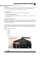
2.2.5 Knob Position Indicator LEDs
The knob position indicator LEDs are used to indicate the currently position of the channel 5 6 position
knob, each indicator corresponds to a flight mode. When the knob changes position, the corresponding
indicator lights up.
2.2.6 Trims
There are 4 trims affecting stick functionality, one for rudder (Channel 4), elevator (Channel 2), throttle
(Channel 3) and ailerons (Channel 1). Each time a trim is toggled, the trim will move one step. It is possible
to make quicker trim adjustments by holding the trim in the desired direction. When the trim position
reaches the middle, the transmitter beeps in a higher tone.
2.2.7 Update Interface
The update interface is used to update the system software. If you want to update the system to the latest
version, contact your local dealer or visit our service and support website for help: www.hobbyking.com.
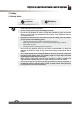
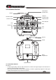
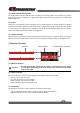
2.3 Receiver Overview
'TZKTTG 9ZGZ[Y/TJOIGZUX
).).6U]KX)UTTKIZUXY
2.3.1 Receiver Antenna
Attention
• For best signal quality, ensure that the receiver is mounted away from motors
or metal parts. Also make sure that the antennas are mounted at a 90 degree
angle to each other.
2.3.2 Status Indicator
The status indicator is used to indicate the power and working status of the receiver.
□
Off: the power is not connected.
□
Lit in red: the receiver is on and working.
□
Flashing quickly: the receiver is binding.
□
Flashing slowly: the bound transmitter is off.
2.3.3 Connectors
The connectors are used to connect the parts of model and the receiver.
□
CH1 to CH8 connectors are used to connect the servos, power or other parts.
□
B/PPM connector is used to connect the bind cable for binding.