
Installation Instructions

NOTE:
If the lights do not work:
1.) Check for loosen or disconnected wires in spot light.
2.) Check that the connection between the connector and the rail is correct.
3.) Check for faulty light bulbs.
Caution: Make sure main power is turned off before serving this fixture.
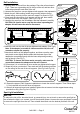
1. Choose one spot light, unscrews the caps from the connector of spot light, then separate the
connector carefully.
CAUTION: Be careful not to snap the wires while separating the connector, this will cause
the wires to disconnect.
2. Attach the main part of the connector onto the rail. Make sure the slot of the connector fits onto the
rail. Then put both halves of the connector back together, and then screw the caps and plastic screws
onto the connector tightly. (See Fig.9 & Fig.10)
CAUTION: To ensure the fixture works correctly, make sure the connection between the adapter
and the rail is correct.
3. Follow steps 1~2 to install the other spot lights onto the rail.
Cap
Knob
Grounding Strip
Screw Driver
Plastic Screw
Cap
Connector
Connector
Rail
Cap
Spot Light
Rail
Rail
Connector of
Spot Light
349-5425 --- Page 3
080715
UANTUS
Q
Glass Holder
Swivel
Socket Ring
2-a
Glass Holder
Glass Shade
Socket Ring
Fig.2-a
Glass Shade
Bulb (Included)
Knob
Cupule
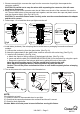
4. Install bulbs (included). See relamping label at socket area or packaging for maximum allowed
wattage.
A. Unscrew the socket ring from the glass holder. (See Fig.12)
B. Attach the glass shade to the glass holder, and then secure it with socket ring. (See Fig.13)
C. Install a bulb (Included). (See Fig.14-a)
a. Attach the cupule to the top surface of the halogen bulb lens. (See Fig.14-b)
b. Insert and twist the bulb (GU10 BASE MR16C BULB ONLY) into the socket by using the cupule.
c. Remove the cupule from the halogen bulb lens by pulling the knob of the cupule.
Note: Do not discard the cupule, it will be needed when replacing the bulb.
Note: Adjust the spotlight head to a desired position by using the swivel.
Caution: Turn off the power and allow the fixture to cool down completely before relamping
the lamp.
5. Turn on the power at the main fuse or circuit breaker box.
Grounding Clip
Brass Clip
Brass Strip
Brass Strip
Fig.9 Fig.10 Fig.11
Fig.12 Fig.13
Fig.14-a
Fig.14-b