
Installation and Operating Guide


18 Equipment Description
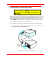
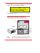
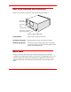
Rear Panel Switches and Connectors
Switches and connectors on the rear of the VLS are shown in Figure 7.
SCSI I/O
Connectors
Fan Filter
Rear
Access Panel
AC Power Connector
and Power Switch
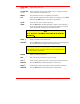
Figure 7. Back of ADIC VLS
Power Switch
Turns on the AC power to the VLS.
AC Power Connector
Plug the VLS AC power cord into this connector.
SCSI I/O Connectors
Connections for the interface cable which connects the
VLS to the computer, to other VLS units and/or to other
devices on the SCSI channel.
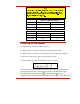
Menu Items
The menus and mode shown at the top of the following diagram are selections
available from the Main Menu. When you choose one of the Main Menu items, a set
of options appears; these options are listed below the Main Menu selections. If an
option has sub-options, these sub-options are listed below and to the right of the
option.