Installation and Operating Guide VLS 4mm Advanced Digital Information Corporation
Copyright Notice © Copyright DGLF 1994 The information contained in this document is subject to change without notice. This document contains proprietary information which is protected by copyright. All rights are reserved. No part of this document may be photocopied, reproduced, or translated to another language without the prior written consent of DGLF.
Copyright Notice (Europe) © Copyright 1995 DGLF Europe All rights reserved. No part of this document may be copied or reproduced in any form or by any means, without prior written permission of DGLF EUROPE, Z.A. du Bel-Air, 21 avenue Saint-Fiacre, 78100 - Saint-Germain en Laye, FRANCE. DGLF EUROPE assumes no responsibility for any errors that may appear in this document, and retains the right to make changes to these specifications and descriptions at any time, without notice.
EMI/RFI Compliance United States – FCC WARNING: This equipment has been tested and found to comply with the limits for a Class B digital device, pursuant to Part 15 of the FCC Rules. These limits are designed to provide reasonable protection against harmful interference in a residential installation. This equipment generates, uses, and can radiate radio frequency energy and, if not installed and used in accordance with the instructions, may cause harmful interference to radio communications.
Declaration of Conformity according to EN 45014 Manufacturer’s Name: Advanced Digital Information Corporation Manufacturer’s Address: 10201 Willows Road NE Redmond, WA 98052 USA 21-23 Av.
Safety Warnings Caution All safety and operating instructions should be read before this product is operated, and should be retained for future reference. This unit has been engineered and manufactured to assure your personal safety. Improper use can result in potential electrical shock or fire hazards. In order not to defeat the safeguards, observe the following basic rules for its installation, use and servicing. 1.
Table of Contents Copyright Notice................................................................................................................... ii Copyright Notice (Europe) ...................................................................................................iii EMI/RFI Compliance........................................................................................................... iv Safety Warnings .....................................................................................
Drive Configuration....................................................................... 23 On-Line Mode............................................................................... 23 Sequential-Access Mode Configuration.......................................... 24 Diagnostics Menu ...................................................................................... 25 Write EEPROM Mode...............................................................................
Quickstart This Section … ❐ provides a quickstart guide for experts who are familiar with installing computer hardware and software.
Note DXU F
Note DGLF bUS_]]U^Tc dXU ecU _V Q^ ²1\d "³ QSdYfU cY^W\U U^TUT dUb]Y^Qd_b ceSX Qc DGLF ` ^ &! !!"$ ! ❐ Connect the AC power cord first to the VLS and then to the AC outlet. Power on the VLS. Power on the host computer. ❐ Place the magazine on the carriage by slipping it over the left “magazine position” pin and then rotating toward the right and pressing into place on the right “magazine position” pin.
Lock 16-Character Display Keypad 9,578$/ /,%5$5< 6<67(0 0(18 $/7 (17(5 (6& /2$' 81/2$' 0$*$=,1( /2&.(' '5,9( % 32:(5 '5,9( $ Locked LED Power LED ❐ Install or confirm the backup software (to run the VLS) on the host computer. ❐ Run any diagnostic tests provided with the backup software to make sure the VLS is communicating correctly with the host computer. You are now ready to run the VLS at a system level.
Chapter 1 Getting Started This Chapter … ❐ covers what you need (and what you need to know) to install the DGLF Virtual Library System. Read this section before you begin installation.
Introduction The Virtual Library System (VLS) is designed for high-capacity, near and off-line storage applications, backup, hierarchical storage management (HSM), and video/design/data file libraries. For the most part, installation is simply a matter of checking all necessary SCSI connections, installing the software (backup or otherwise) and applying power. The defaults set at the factory should be sufficient for most applications. Requirements 8 .0 in. 20 .3 cm 15 .8 in . 40 .1 cm 1 7.4 in 4 4.
❐ Necessary tools: No special tools are required to install the VLS. If you are installing a host adapter (SCSI controller) card at this time, refer to the installation manual for your host adapter. Unpack and Inspect Caution If the operating environment differs from the storage environment by 15° C (30° F) or more, let the unit acclimate to the surrounding environment for at least 12 hours. ❐ Unpack all items from the carton.
Equipment Description The VLS Unit The DGLF VLS is a fully automated, high performance, high capacity, mass storage system designed with a removable data cassette magazine. The door can be locked to deactivate the unit's keypad, assuring only authorized removal of the magazine and media. In addition, to protect the unit, data and media, the VLS will not operate unless the door is closed.
Media The 4mm VLS uses 4mm DDS data cassettes. Before inserting the cassette into the magazine check the position of the write-protect switch. Set all switches to the enabled position – hole closed (refer to Figure 2). (The write-protect switch enables or disables the ability to write [or delete] files on the data cassette.) Caution Only cassettes labeled "DDS" should be used. Never use audio DAT cassettes, because the media is not certified.
Cleaning Cassette The tape heads should be cleaned after every 8 to 10 hours of tape motion or when the Media Caution indication is displayed. A cleaning cassette (ADIC 39-1028-01) is shipped with your DGLF VLS. Discard it after approximately 20 uses and replace it with the same or equivalent type cleaning cassette. See Cleaning the Drive Head later in this manual. Figure 3. 4mm Cleaning Cassette System Software A variety of backup and data storage software is available for use with the VLS.
Preparing the Host Computer System Power Off the Computer ❐ Turn off the power switch. ❐ Unplug the cord from the AC outlet. Confirm and/or Install the SCSI Host Interface The VLS must be connected to either an integrated SCSI host or a SCSI interface (host adapter) card installed in the computer – either directly to the I/O connector on the card or as part of an existing SCSI chain. The SCSI interface must be installed before you connect the VLS.
Blank Page 8 Getting Started
Chapter 2 Connecting the VLS This Chapter … ❐ provides instructions for physically connecting your VLS to your host system. ❐ steps you through the final phase of the installation process.
Connecting the Interface Cables Note DXU Y^dUbVQSU SQR\Uc ]ecd RU cXYU\TUT ° DGLF SQ^ ce``\i i_e gYdX dXU S_bbUSd di`U c Make sure the interface cable you are using has the appropriate connectors on each end. If the host computer's SCSI connector is different from that on the VLS, you will need to obtain a different cable than the one supplied with the unit. Consult your dealer or DGLF Customer Assistance if you need help.
Note DXU RQY\ \_S[c Qd R_dX U^Tc _V dXU C3C9 SQR\U ]ecd RU cUSebU\i VQcdU^UT Y^ _bTUb V_b dXU F
Connecting More Than One VLS If you are connecting additional VLS units on the same SCSI channel, simply attach each subsequent unit to the previous unit with an interface cable. Make sure all cables are properly secured. You can attach up to seven devices on each SCSI channel. 2 V L S u n its (O n sam e SC SI Ch annel) *F errite B ead Term inator SCSI In terface C able I/O C on necto rs H o st C o m p u te r Figure 5.
Note GXU^ S_e^dY^W C3C9 TUfYSUc [UU` Y^ ]Y^T dXQd Q F
the drive is configured and on-line, but is not aligned with the Media Picker. The symbol indicates that there is no configured drive in that position. The in the 5th character position for each drive indicates that the VLS does not know if a cartridge is currently loaded in that drive. If the VLS had loaded a cartridge into a drive prior to shut-down, this character and the one proceeding it would reflect the slot number of the magazine that the cartridge was loaded from (01 to 15).
Chapter 3 Equipment Description This Chapter … ❐ describes the switches, indicators and connectors on the front and rear of the VLS. ❐ describes the various functions available via the front panel buttons. ❐ describes the power-up procedure and messages on the front panel LED display.
Once your VLS has been connected to your host computer system and the software has been installed, the VLS is ready for use. Just turn on the power switch, place a magazine on the carriage and press ALT and then LOAD.
Power LED (green) Lights when power is on. Locked LED (green) Lights when door is locked. The magazine, drive, or keypad cannot be accessed while the Locked LED is on. MENU Press this button to enter or exit Off-line mode menus ALT Selects alternate function for another button. For example, press the ALT button to activate the load function. button and the UP Up Selects previous item or value in the menu.
Rear Panel Switches and Connectors Switches and connectors on the rear of the VLS are shown in Figure 7. SC SI I/O C onnectors Fan Filter R ear A ccess Panel A C P ow er Connector and Pow er Sw itch Figure 7. Back of ADIC VLS Power Switch Turns on the AC power to the VLS. AC Power Connector Plug the VLS AC power cord into this connector. SCSI I/O Connectors Connections for the interface cable which connects the VLS to the computer, to other VLS units and/or to other devices on the SCSI channel.
Configuration Menu Diagnostics Menu Buzzer Configuration Error Counters ErrAlarm Yes/No Event Counters Kybd Yes/No Operation Log SCSI ID Config Firmware Revision Drive B (0-7) Serial Number Drive A (0-7) Position Drive AC (0-7) Position Magazine SCSI Parity Parity Check Load Medium Yes/No Off-Line Time Max time Write EEPROM Mode Unload Medium Unload Drives 1-99 min Drive Configuration Drv A Yes/No Drv B Yes/No On-Line Mode* Random / Sequential Sequential Mode Cfg* First (0-
To access the Off-Line menu, press the MENU button. The display will appear as follows: Use the UP or DOWN buttons to scroll through the menu. Press ENTER to select a displayed item. Use the RIGHT or LEFT buttons to scroll through fields on the same line. To exit the Off-Line menu press the MENU button.
To enable the error alarm use the LEFT button to select the ErrAlarm field. Use or DOWN to select "Y" to enable alarm or "N" to disable alarm. When UP Error Alarm mode is enabled, a continuous alarm tone will sound in the event of an error message. The alarm will sound until the condition that caused the error has been removed or any key is pressed. To clear an error message from the display, press ALT and ENTER.
SCSI Parity Lets you enable or disable the reporting of SCSI parity. Press ENTER to access this function. Use UP or DOWN to select "Y" to enable the reporting of parity check or "N" to disable the reporting of parity check. Press ENTER to activate the change. Note C3C9 @QbYdi TUVQe\d* @QbYdi 3XUS[* > Off-Line Time Lets you set the number of minutes the VLS will remain in the Off-Line mode.
Drive Configuration This function lets you enable or disable which drives are on-line. Use LEFT or RIGHT to select the drive you wish to change. Use UP or DOWN to select "Y" to put the drive on-line or "N" to disable the drive. If you have only one drive installed, you cannot access the Drv B field.
Note 9V i_e XQfU R_dX TbYfUc _^ \Y^U i_e gY\\ ^_d RU QR\U d_ QSSUcc dXYc Ve^SdY_^ DXU c_VdgQbU i_e ecU gYdX dXU F
The Loopback (LPBK) mode determines what happens when the last cassette has been filled. If you select "Y" for "Lpbk" the designated first cassette will be loaded into the tape drive after the last cassette has been filled and ejected. If you select "N" an error message will be issued and the backup will stop.
Write EEPROM Mode The Write EEPROM Mode is used whenever you upgrade the VLS firmware. Refer to Appendix C in this manual for additional information.
Chapter 4 Operation and Maintenance This Chapter … ❐ describes normal operation features of the VLS ❐ provides details on the media and magazine ❐ explains normal maintenance procedures 27
The VLS unit is composed of one or two DAT drives and the robotics that control the drive(s), magazine and media. The drive(s) are unmodified. The drive status LEDs function per the manufacturer’s specifications. No routine maintenance is required – apart from cleaning the heads after approximately each 8 to 10 hours of tape motion or when the Media Caution indication is displayed on the drive LEDs (see Cleaning the Drive Head later in this manual).
Write-Protect Switch Closed (Unprotected) Open (Protected) Inserting Data Cassettes into the Magazine The magazine for the 4mm VLS holds fifteen 4mm cassettes. It includes a clear dust cover to protect the cassettes and for easy storage. See Figure 8. Insert each cassette into a slot of the magazine making sure that the write-protect tab is on the top and the cassette faces toward you when the magazine is loaded onto the carriage of the VLS (as illustrated).
M a g a zin e C o ve r W rite -P ro te ct S w itc h D a ta C a s se tte s M a g a z in e O p e n sid e o f m a g a zin e (to w a rd s V L S ) C lo se d sid e o f m a g a z in e Figure 8. VLS Magazine The open side of the magazine faces the VLS. Make sure each cassette touches the bottom floor of the magazine. Do not use wrap-around labels on the individual cassettes. Most labels use a removable adhesive and have a tendency to curl or tear after multiple uses. This can jam the movement of the VLS.
Inserting the Magazine into the VLS Note 4_ ^_d QddU]`d d_ `\QSU Q S_fUbUT ]QWQjY^U _^d_ dXU F
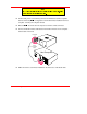
639181 Left "magazine position pin" Figure 10. Placing the Magazine onto the VLS ❐ Push the right side of the magazine over the right hand magazine position pin until you hear a click. See Figure 11. Note I_e ]Qi ^UUT d_ Q``\i T_g^gQbT `bUccebU Qc i_e c\Y` dXU ]QWQjY^U _fUb dXU bYWXd ]QWQjY^U `Y^ Q^T dXU^ `bUcc dXU ]QWQjY^U Y^d_ `\QSU gYdX i_eb Y^TUh VY^WUb Figure 11.
The magazine will snap into place. If you don't hear a click, make sure that the slot on the right side of the magazine has slipped around its magazine position pin and is not just sitting on top of it. The magazine will not load correctly in this position. Loading the Magazine Once you have placed the magazine on the carriage, the VLS must initiate a loading process.
Attempting to Load the Magazine with a Cassette Already in Drive Random Mode: If the cassette was loaded manually, it must be unloaded manually – before you attempt to have the VLS load the magazine. Refer to the next section for manual removal of a cassette. If the VLS robotics was used to load the cassette via applications software, attempting to "load magazine" from the keyboard will fail – the unit will remain on-line.
Manually Removing a Cassette Loaded in the Drive ❐ Press ALT and then UNLOAD. This will place the magazine in the unload position. ❐ Open the VLS door. Remove the magazine from the carrier. ❐ Press the eject button on the drive (see Figure 12). It may take 30 seconds or more for the drive to eject the cassette. D rive E je ct B u tton Figure 12. Typical Position of Drive Eject Button.
Removing the Magazine from the VLS Before physically removing the magazine from the carrier, you must first initiate the UNLOAD procedure. ❐ Make sure there is no cassette in the drive. If there is, go to the next procedure, Removing the Magazine while a Cassette is in Drive Note I_e SQ^^_d Y^YdYQdU Q^ E>
❐ Place the transparent cover over the magazine and store the unit in a cool, dry place. Note =Q[U cebU i_e XQfU \QRU\UT UQSX SQccUddU Qc d_ ]QWQjY^U Q^T c\_d ^e]RUb 9V i_e Tb_` dXU ]QWQjY^U gYdX_ed dXU S_fUb _^ dXU SQccUddUc gY\\ VQ\\ _ed Removing the Magazine while a Cassette is in the Drive If you wish to remove the magazine but there is a cassette in the drive, do the following: ❐ Open the VLS door. ❐ Press the eject button on the drive (see Figure 12). ❐ Close the door of the VLS.
❐ Insert the cassette into the drive opening with the label side to your left and the write-protect switch positioned down. Apply steady pressure on the back of the cassette until the autoloading mechanism takes the cassette and loads it into the drive. The cassette is now in a semi-loaded state. If the humidity level is acceptable, the drive threads the tape, initiates a load sequence and goes on-line. The drive will take approximately 20 seconds to load the cassette.
Removing a Cassette from the Magazine The data cassettes easily slip into and out of the slots of the magazine. To remove a cassette, simply grasp it with two fingers and pull up. Make sure each cassette is labeled so you know the contents (and where it belongs in the magazine sequence). Storing the Magazine Store magazines in a dry, cool environment. Always keep the dust cover on the magazine. The removable magazine allows for long-term archiving or off-site safety storage of groups of data.
Clean the drive head and tape path after every 8-10 tape motion hours (about once a week under typical use). You should also clean after the first use of a new tape cassette. As an absolute visual reminder, the drive status LEDs will flash the Media Caution indication during cassette load/unload operations after approximately 24 hours of head-tape motion since the last cleaning. To see the status LEDs, the magazine must be in the unloaded position and you must look at the drive (see Figure 13).
flash amber during cassette load/unload operations. Figure 14 shows a sample cleaning cassette with the label on which to write the date of each use. Figure 14. Representative Cleaning Cassette Caution DO not attempt to RE-USE or REWIND the cleaning cassette after all the cleaning cycles (approx. 20) have been used. ❐ Insert the cleaning cassette into the drive opening (see Figure 15). The drive will load the cassette and automatically begin the cleaning process.
Figure 15. Inserting the Cleaning Cassette into the Drive. ❐ When the cleaning is finished the drive will automatically eject the cassette. Remove the cleaning cassette and write the date on the label so you have a record of how many times it has been used and when. ❐ To confirm that a cleaning was done, look at the LEDs on the front panel of the drive. If the cleaning cycle was successful, the LEDs will be off. If the cleaning cycle was not performed, the LEDs will continue to flash.
Caution Cleaning cassettes are considerably more abrasive to the drive's recording heads than standard data cassettes. Usage should be kept within the recommended limits, or the warranty may not be applicable to the affected equipment. The VLS is once again ready for use. Caution If you encounter a hard error during normal operation, first try a new 4mm data cassette. If this solves the problem, continue on with the new cassette. If the symptom persists, try one cleaning cycle with the cleaning cassette.
Blank Page 44 Operation and Maintenance
Chapter 5 Troubleshooting and Diagnostics This Chapter … ❐ contains some general suggestions to aid you in solving problems – should you ever run into them. ❐ includes information on error codes and the built-in diagnostics.
VLS Error Messages If any component of the VLS is not communicating correctly, a warning message will appear on the front display. A list of error messages in included on the following page. If the error you see is not on this list, please call DGLF Customer Assistance. In all cases, after removing the cause of the problem (or if you can't find a cause) push MENU to return the VLS to the on-line condition. f the error message is not listed, try to return to the on-line mode by pressing ALT and/or ENTER.
Error Messages Note C_]U _b Q\\ _V dXU Ubb_b ]UccQWUc ]Qi bUce\d Vb_] _^U _b ]_bU S_^TYdY_^c DXU TUVY^YdY_^ WYfU^ Yc V_b Q cY^W\U S_^TYdY_^ _^\i 9V i_e RU\YUfU dXQd dXU S_^TYdY_^ gXYSX SQecUT i_eb Ubb_b ]UccQWU Yc _dXUb dXQ^ dXU TUVY^YdY_^ `\UQcU SQ\\ DGLF 3ecd_]Ub 1ccYcdQ^SU Qd* " & ((# $#%' Error Name Description Source location empty The source location was empty when the VLS attempted to pick a cartridge from it.
Error Name Description Unable to load medium in drive The VLS attempted to load a cartridge into a drive but failed, possibly due to a drive positioning error. Door has been opened The front door of the VLS had been opened, but is now closed. Door is open The front door of the VLS is open. This error will appear whenever the front door is opened while power is on.
Drive Warning Signals The 4mm drives used in the VLS employ front panel LEDs to indicate SCSI interface activity, drive fault conditions, and cartridge status. Figure 16 is a close-up of the Sony SDT-5000 (SDT-7000/SDT-9000 are the same) drive and the location of the warning LEDs. The LEDs on all other drives are located in approximately the same place. Refer to the following tables for descriptions of the methods employed by different drives to indicate activity, status, and fault conditions.
Hewlett Packard C1533A/C1537A Drive Status LEDs Tape LED (bottom) Clean LED (top) Meaning Flashing green (½ sec on, ½ sec off) Off Cartridge activity — load or unload Fast flashing green (¼ sec on, ¼ sec off) Off SCSI activity — read or write Steady green Off Off Flashing amber (½ sec on, ½ sec off) Cartridge loaded, drive online Media Caution Signal Off Flashing green (½ sec on, ½ sec off) Steady amber Off Drive fault Self-test in progress Table 3.
Sony SDT-5000/SDT-7000/SDT-9000 Drive Status LEDs Busy LED (Top) Tape LED (Middle) Status LED (Bottom) Off Off Off On Fast flashing (¼ sec on, ¼ sec off) Fast flashing (¼ sec on, ¼ sec off) Off Off Fast flashing (¼ sec on, ¼ sec off) Fast flashing (¼ sec on, ¼ sec off) On Off Off Off On On On Off Off Fast flashing (¼ sec on, ¼ sec off) * On Off On On * Long, slow flashing (3½ sec on, ½ sec off) * * * Long, slow flashing (3½ sec on, ½ sec off) * * * * Flashes once for ¼ sec then sta
Environmental Considerations For best performance of your VLS, please observe the following guidelines: ❐ If you expose cassettes to temperatures outside the operating limits – 40-113°F (540°C) – stabilize them by leaving the cassettes in the operating temperature for a minimum of two hours before you use them. ❐ Avoid temperature problems by ensuring that the VLS's side and rear are not obstructed so that the drive has adequate ventilation. ❐ Position the VLS where the temperature is relatively stable (i.
❐ If at all possible, call while at your computer, with DGLF 's system installed and turned on. ❐ If running on a network, have all relevant information available (i.e. type, version #, network hardware, etc.).
Return for Repair RMA (Return Merchandise Authorization) When you and DGLF Customer Assistance have determined that you need an RMA number (see previous section When You Call DGLF Customer Assistance). be prepared with the following information: • Model number, serial number, and a brief, descriptive explanation of the problem. • Complete address information (be sure you give any mail stops or special codes at the time the RMA is issued).
Appendix A Installing the Ferrite Bead This Appendix … ❐ describes how to install a ferrite bead (supplied) on the SCSI cable to assure compliance with EMI/RFI suppression specifications with dual VLS installations.
If you are using two or more VLS units on the same SCSI channel, you must install a ferrite bead on the interface cable between the units. ❐ Clip the clamp-on bead on the cable at any point between the two units. Refer to Figure 17. Ferrite Bead 2 VLS units (On same SCSI Channel) SCSI Interface Cable Host Computer 639104 Figure 17. Installing the Ferrite Bead The ferrite bead is required to satisfy the EMI/RFI suppression limits. The bead does not affect the functionality of your system in any way.
Appendix B Diagnostics Menu This Appendix … ❐ describes the built-in diagnostic functions as available via the Diagnostics Menu 57
One of the most valuable features of the VLS is the extensive built-in diagnostics. In this Appendix we discuss each of the Diagnostic functions available through the front panel keypad. To access the Diagnostics Menu, press the MENU button. The display will read as follows: Press DOWN to access the Diagnostics Menu. Press ENTER; a display similar to the following will appear.
Error Counters Provides a chronological listing (beginning with the last error issued) of the errors encountered by the VLS system. These are VLS internal hardware/firmware errors. This register records each error name and assigns it a sequential number. nnnnnnnn = Counter name. ccccc = Counter value (0 - 65535) Event Counters Provides a listing of the various VLS operations and how many times they have occurred. nnnnnnnn = Counter name.
NNN = Logged operation number (1-255). When log is full, new operations are logged in as operation 255, scrolling the old operation 1 off the log.
)LUPZDUH 5HYLVLRQ Provides a record of the internal revision date and number. This information is vital for trouble shooting problems. Be prepared to provide this information to your reseller's Customer Assistance personnel if you ever need to talk with them. The following chart shows what each character in the sequence means.
l = Modification level 3RVLWLRQ 'ULYH Use the Position Drive function to line a drive up with the cassette window. Select drive A or B using UP or DOWN . Press ENTER to activate. 3RVLWLRQ 0DJD]LQH Use the Position Magazine function to line up the magazine with the on-line drive at a particular slot. Select the slot number using UP or DOWN . Press ENTER to activate. This option is usually used for diagnostics only by a trained technician.
8QORDG 0HGLXP The Unload Medium function is used to line up the magazine with a particular drive at a particular slot so that the cassette will be placed in that slot when ejected. or RIGHT to select the desired field. Select the slot or drive using Use LEFT UP or DOWN . Press ENTER to activate.
5. Waits until door is opened, then closed (because operator should have opened door, pressed eject button on drive, then closed door). 6. Checks that cartridge in transit sensor detects presence of media (because drive ejected cartridge). 7. Returns media to magazine. 8. Aligns second drive with cartridge window (if VLS thinks both drives contain media). 9. Repeats steps 2 through 7. If the VLS thinks that the drive(s) are empty it will display: “All configured drives are empty”.
Appendix C Glossary This Appendix … ❐ contains terms and definitions of common expressions used with the VLS and the 4mm drive.
66 ALT This button is used to activate the load/unload functions on the front panel. byte 8 bits or one character. C Celsius (Centigrade). cassette A storage medium item. A cassette is sometimes called a tape or cartridge and is capable of storing vast amounts of magnetically-written data. Some cassettes can store more than 24 GB of data. The 4mm drive in the VLS uses data-grade DDS cassettes. cleaning cassette Media used to clean the drive heads and tape path. cm Centimeter (0.3937 inches).
DDS-3 drive Drive that may be used in the 4mm VLS. It is an enhanced 4mm digital helical-scan cassette tape subsystem. FCC Federal Communications Commission ferrite bead a device required to suppress radio noise in certain conditions to meet specifications GB gigabyte (1 GB = 1,024 Megabytes) HSM Hierarchical Storage Management – a system where different types of storage medium are used based on cost and time efficiency. For example, for fastest access, data is usually stored on a local drive.
68 load The process where the VLS checks each slot to see if a cassette is physically present, and if so, whether the orientation of the cassette in the magazine is correct. It also places the magazine in position for the first cassette to be inserted into the drive. In sequential mode, the first cassette is physically inserted into the drive. magazine The item that holds the tape cassettes for use within the VLS. The 4mm magazine holds 15 cassettes. The magazine provides long-term storage of cassettes.
SCSI bus Signal path or line shared by the devices on the same SCSI channel. Information is often sent to all devices throughout the same bus; only the device to which it is addressed will accept it. sequential-access mode The cassettes in the magazine are inserted into the drive in a sequential manner, i.e. number 1 is first, number 2 is second, etc. When the last cassette is ejected from the drive, the sequence will either stop and the VLS will issue an error message or loop back to the first cassette.
Blank Page 70 Glossary
Appendix D Specifications This Appendix … ❐ contains terms and definitions of common expressions used with the VLS and the 4mm drive.
Specifications Drive Data Capacity: Up to 24 GB per 125-meter DDS-3 cassette (DDS-3 drive w/2:1 compression) Up to 360 GB per 15 cassette magazine (DDS-3 drive w/2:1 compression) Type: HP model C1533A (DDS-2) HP model C1537A (DDS-3) Sony model SDT-5000 (DDS-2) Sony model SDT-7000 (DDS-2) Sony model SDT-9000 (DDS-3) (Optional dual drives available) Data Transfer Rate: Up to 288 MB/min. w/2:1 compression (dual Sony SDT-9000) Up to 240 MB/min.
Physical Dimensions: 17.4" (w) x 15.8" (d) x 8.0" (h) Weight: 30 lb. (32 lb. with dual drives) Power Consumption Less than 65 Watts Environment Electrical: 100-240 VAC Automatic AC line voltage selection Temperature: 10° C to 40° C (Operating) -40° C to 70° C (Storage/Shipping) Humidity: 20% to 80% (Operating) 5% to 95% (Storage/Shipping) 0.25g (5-500 Hz) (Operating) 0.
Blank Page 74 Specifications
Index 75
—A— alarm mode, 20 alarm sound, 20 archiving, 39 —B— backup software, xii, 2, 6, 14, 16 bail locks, 10, 11 Busy LED, 51 Buzzer Configuration, 19, 20, 21 —C— cassette label, 30, 39 Changer Cassette Change Time, 71 Changer Indicators/Controls, 71 Changer Interface, 71 Changer Magazine Capacity, 71 Changer Maintenance, 71 Changer Media Type, 71 Clean LED, 50 cleaning cassette, 6, 37, 39, 40, 41, 42, 43, 66, 71 cleaning confirmation, 42 cleaning cycle, 39, 40 Cleaning the Drive Head, 6, 28, 39 Cleaning the En
—G— gripper arm, 38, 60 —H— Hierarchical Storage Management, 2, 67 host computer, x, xii, 2, 7, 10, 13, 14, 16, 67, 68 HSM, 2, 67 humidity, 51, 72 —I— I/O connector, 7 Inserting Data Cassettes into Magazine, 29 Inserting Magazine into VLS, 31 Installing the Backup Software, 14 Installing the SCSI Host Interface, 7 interface cable, iv, 10, 12, 56 —L— Load Magazine, 60 Load Medium, 19, 58, 62 Loading Individual Cassette, 37 Loading Magazine with Cassette in Drive, 34 Loading the Magazine, 33 Locked LED, 71
—R— random-access mode, 2, 13, 23, 24, 33, 34, 68, 69 Rear Panel AC Power Connector, 18 Rear Panel Power Switch, 18 Rear Panel SCSI I/O Connectors, 18 Rear Panel Switches and Connectors, 18 Removing a Cassette Loaded in Drive, 35 Removing Cassette from the Magazine, 39 Removing Magazine from VLS, 36 Removing Magazine with Cassette in Drive, 36, 37 Return for Repair, 54 Return Merchandise Authorization, 54, 68 RMA, 54, 68 RMA number, 54, 68 Sequential-Access Mode Configuration, 19, 20, 24 Serial Number, 19,