
User's Manual

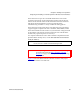


Table Of Contents
- Contents
- Figures
- Tables
- Preface
- Tape Drive Product Information
- SDLT 600 Tape Drive Specifications
- Installing Your Tape Drive
- Warranty Note
- Safety, Handling, and ESD Protection
- Pre-Installation Guidelines
- Configuring and Installing an Internal Tape Drive with SCSI Interface
- Configuring and Installing an Internal Tape Drive with Fibre Channel Interface
- Configuring and Installing a Tabletop Tape Drive with SCSI Interface
- Configuring and Installing a Tabletop Tape Drive with SCSI Interface
- Confirming the Installation
- Using Your Tape Drive
- Regulatory Compliance
- Super DLTtape I and Super DLTtape II Data Cartridges
- DLTtape VS1 Data Cartridge
- Glossary
Chapter 3 Installing Your Tape Drive
Configuring and Installing a Tabletop Tape Drive with SCSI Interface
SDLT 600 Product Manual 62
Installing the SCSI
Tabletop Tape Drive
3
Tabletop tape drive installation consists of connecting SCSI bus and
power cables.
Figure 13
shows the location of the two SCSI bus connectors and power
connector on the back of the tabletop tape drive.
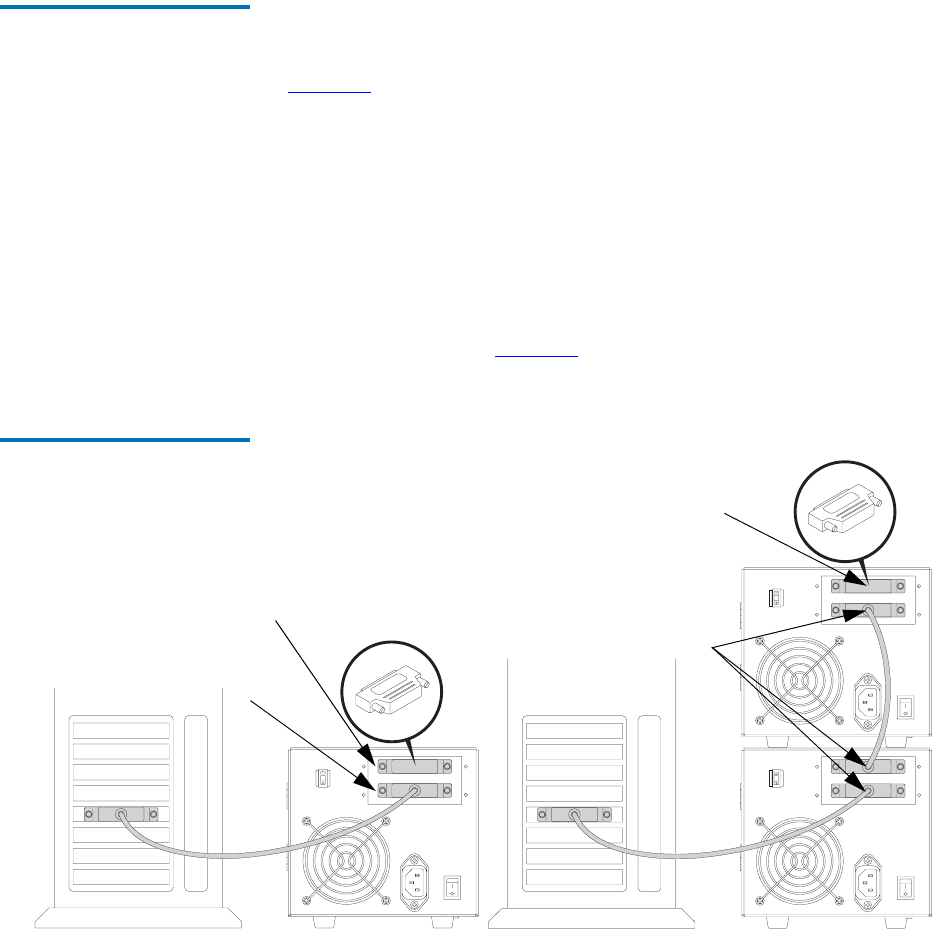
SCSI Cables
3
You can connect the SCSI bus cable leading from the host adapter to
either of the tape drive SCSI connectors. If the tape unit is the last device
on the bus, then you should install a SCSI terminator on the open
connector. If the bus continues from the tape drive to another SCSI
device, then install a SCSI bus cable between the open connector and the
next device on the bus. Figure 15
illustrates these two connection
methods.
Figure 15 Cabling Options for
the SCSI Tape Drive Tabletop
Model
3
3
3
A) Cabling For Single Tape Drive Connection
B) Cabling For Daisy-Chain Connection
SCSI B cable
SCSI terminator
connections
connection
SCSI cable
SCSI terminator
connection
connection