
User's Manual


Table Of Contents
- Contents
- Figures
- Tables
- Preface
- Tape Drive Product Information
- SDLT 600 Tape Drive Specifications
- Installing Your Tape Drive
- Warranty Note
- Safety, Handling, and ESD Protection
- Pre-Installation Guidelines
- Configuring and Installing an Internal Tape Drive with SCSI Interface
- Configuring and Installing an Internal Tape Drive with Fibre Channel Interface
- Configuring and Installing a Tabletop Tape Drive with SCSI Interface
- Configuring and Installing a Tabletop Tape Drive with SCSI Interface
- Confirming the Installation
- Using Your Tape Drive
- Regulatory Compliance
- Super DLTtape I and Super DLTtape II Data Cartridges
- DLTtape VS1 Data Cartridge
- Glossary
Chapter 3 Installing Your Tape Drive
Configuring and Installing an Internal Tape Drive with Fibre Channel Interface
SDLT 600 Product Manual 57
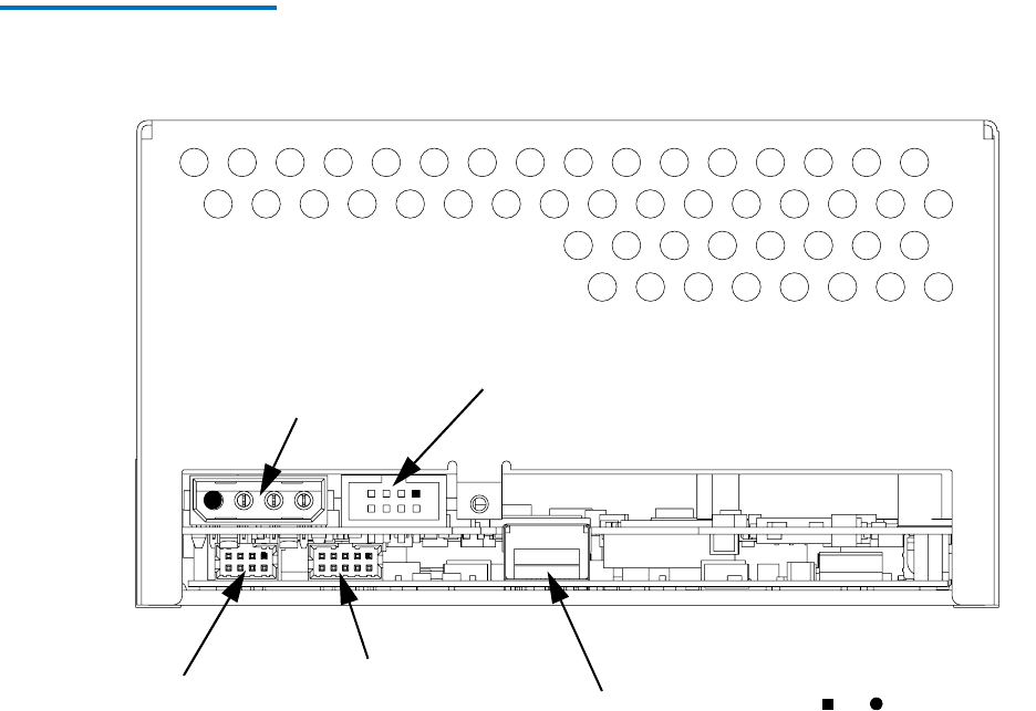
Figure 11 Internal Fibre Channel
Tape Drive Connectors and
Jumpers
Follow these steps to connect a Fibre Channel tape drive:
1 Secure the tape drive.
2 Connect the power.
3 Connect the library/loader (optional).
4 Connect the Fibre Channel cable.
Each of these steps is discussed in the subsections that follow.
Controller Diag Port (8 pin)
(Diagnostic use only)
Fibre Channel
Power Connector
(4 pin)
Fibre Channel
Loader Connector
RS-422 (8 pin)
Port
Jumper Block
Denotes Pin # 1
or