
User's Manual


Table Of Contents
- Contents
- Figures
- Tables
- Preface
- Tape Drive Product Information
- SDLT 600 Tape Drive Specifications
- Installing Your Tape Drive
- Warranty Note
- Safety, Handling, and ESD Protection
- Pre-Installation Guidelines
- Configuring and Installing an Internal Tape Drive with SCSI Interface
- Configuring and Installing an Internal Tape Drive with Fibre Channel Interface
- Configuring and Installing a Tabletop Tape Drive with SCSI Interface
- Configuring and Installing a Tabletop Tape Drive with SCSI Interface
- Confirming the Installation
- Using Your Tape Drive
- Regulatory Compliance
- Super DLTtape I and Super DLTtape II Data Cartridges
- DLTtape VS1 Data Cartridge
- Glossary
Chapter 3 Installing Your Tape Drive
Configuring and Installing an Internal Tape Drive with SCSI Interface
SDLT 600 Product Manual 49
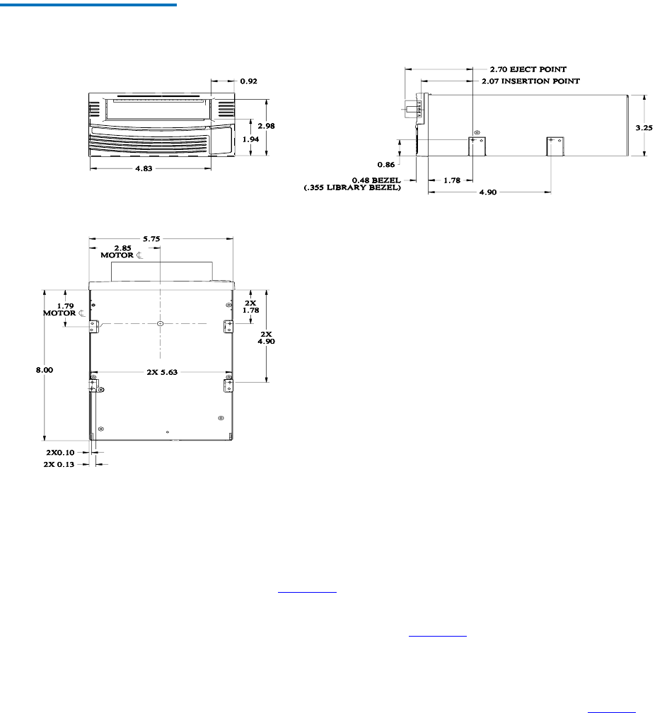
Figure 9 Internal Tape Drive
Mounting Locations – Front, Side,
and Bottom Dimensions
Connecting the Internal Tape Drive Cables 3
This section discusses three connectors on the back of the internal SDLT
600 tape drive: 1) SCSI, 2) power, and 3) optional library/loader
connectors. Figure 10
shows some typical AC power cord connectors
used for the tabletop model.
SCSI and Power Connectors
3Figure 13 on page 60 shows the pin
orientation for the 68-pin SCSI connector and 4-pin power connector
located on the back of the internal tape drive.
The tables list pin assignments for the two possible SCSI connectors:
Multi-mode Single-Ended (MSE)/Single Ended (SE) mode in table 27
,