
User's Manual
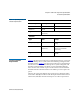
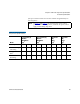


Table Of Contents
- Contents
- Figures
- Tables
- Preface
- Tape Drive Product Information
- SDLT 600 Tape Drive Specifications
- Installing Your Tape Drive
- Warranty Note
- Safety, Handling, and ESD Protection
- Pre-Installation Guidelines
- Configuring and Installing an Internal Tape Drive with SCSI Interface
- Configuring and Installing an Internal Tape Drive with Fibre Channel Interface
- Configuring and Installing a Tabletop Tape Drive with SCSI Interface
- Configuring and Installing a Tabletop Tape Drive with SCSI Interface
- Confirming the Installation
- Using Your Tape Drive
- Regulatory Compliance
- Super DLTtape I and Super DLTtape II Data Cartridges
- DLTtape VS1 Data Cartridge
- Glossary

Chapter 2 SDLT 600 Tape Drive Specifications
Functional Specifications
SDLT 600 Product Manual 26
(The power drawn in these two modes is similar enough that they are
listed together.)
Table 16 Current and Power
Requirements (SCSI Interface)
Note: In table 16 and table 17, the current and DC power values
pertain to the internal tape drive, while the AC power values
apply to the tabletop tape drive.
Mode
5 V Current (A)
MaxPk
1
MaxMean
2
Typ
3
12 V Current (A)
MaxPk
1
MaxMean
2
Typ
3
DC Power
(W)
Max
4
Typ
5
AC Power
(W)
Max
6
Typ
7
Standby/Idle 2.6 2.6 2.4 0.2 0.1 0.1 14 14 47 45
Media Loading/
Unloading
6.2 5.3 3.4 2.7 0.9 0.7 30 26 64 56
600 Write– Motor
Start
8
4.3 4.0 3.7 1.3 0.3 0.3 23 22 51 48
600 Write–
Streaming
5.4 5.1 4.9 0.7 0.5 0.4 30 30 65 63