SDLT 220 and SDLT 320 Product Manual Copyright Copyright © 2004 by Quantum Corporation. All rights reserved. Document Origination: Boulder, Colorado, USA. Trademarks Quantum, the Quantum logo, and the DLTtape logo are trademarks of Quantum Corporation registered in the U.S.A. and other countries. DLTtape, DLTSage, Value DLTtape, and Super DLTtape are trademarks of Quantum Corporation.
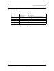
SDLT 220 and SDLT 320 Product Manual Revision History Revisions made to this document are listed below in chronological order. Document Release Date Summary of Changes A March 14, 2002 Create document. A01 April 29, 2002 Initial release. Note: This manual supersedes Quantum document 81-80000-01. A02 April 30, 2002 Minor changes. A03 October 30, 2002 Scheduled update. A04 March 12, 2004 Maintenance update. Added information about tape density selection. Updated Appendices A and B.
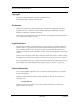
SDLT 220 and SDLT 320 Product Manual User Manual Statements for Class A Equipment (Internal Tape System) This equipment generates, uses, and may emit radio frequency energy. The equipment has been tested and found to comply with the limits for a Class A digital device, pursuant to Part 15 of the FCC rules. These limits are designed to provide reasonable protection against radio frequency interference in a commercial installation.
SDLT 220 and SDLT 320 Product Manual User Manual Statements for Class B Equipment (Tabletop Tape System) This equipment has been tested and found to comply with the limits for a Class B digital device, pursuant to Part 15 of the FCC rules. These limits are designed to provide reasonable protection against harmful interference in a residential installation.
SDLT 220 and SDLT 320 Product Manual from device to device and needs to be obtained from the EMC (Electromagnetic Compatibility) group or product manager. This Class B digital apparatus complies with Canadian ICES-003. Cet appareil numérique de la classe B est conforme à la norme NMB-003 du Canada.
Table of Contents CHAPTER 1 Introduction. . . . . . . . . . . . . . . . . . . . . . . . . . . . . . 1-1 Purpose and Scope. . . . . . . . . . . . . . . . . . . . . . . . . . . . . . . . . . . . . . . . . . Referenced Documents . . . . . . . . . . . . . . . . . . . . . . . . . . . . . . . . . . . . . . Related Documents . . . . . . . . . . . . . . . . . . . . . . . . . . . . . . . . . . . . . . . . . Structure of this Manual . . . . . . . . . . . . . . . . . . . . . . . . . . . . . . . . . . . . .
Table of Contents SDLT 220 and SDLT 320 Product Manual Super DLTtape I Data Cartridge Module . . . . . . . . . . . . . . . . . . . . . Key Differences Between the SDLT 220 and the SDLT 320 . . . . . . . . Quantum Diagnostics Tools . . . . . . . . . . . . . . . . . . . . . . . . . . . . . . . . . TapeAlert . . . . . . . . . . . . . . . . . . . . . . . . . . . . . . . . . . . . . . . . . . . . . . . . CHAPTER 3 2-10 2-11 2-12 2-13 Drive Specifications . . . . . . . . . . . . . . . . . . . . . . .
SDLT 220 and SDLT 320 Product Manual CHAPTER 4 Table of Contents Installing Your Tape Drive . . . . . . . . . . . . . . . . . . . 4-1 Safety, Handling, and ESD Protection . . . . . . . . . . . . . . . . . . . . . . . . . . 4-2 Safety Precautions . . . . . . . . . . . . . . . . . . . . . . . . . . . . . . . . . . . . . . . 4-2 Handling . . . . . . . . . . . . . . . . . . . . . . . . . . . . . . . . . . . . . . . . . . . . . . . 4-3 Electrostatic Discharge Protection . . . . . . . . . . . . . . . . . . . .
Table of Contents SDLT 220 and SDLT 320 Product Manual Forcing Tape Density with MODE SELECT Parameters . . . . . Tape Density and the Drive Density Indicator. . . . . . . . . . . . . . . . . Troubleshooting. . . . . . . . . . . . . . . . . . . . . . . . . . . . . . . . . . . . . . . . . . . POST Troubleshooting. . . . . . . . . . . . . . . . . . . . . . . . . . . . . . . . . . . Over Temperature Condition . . . . . . . . . . . . . . . . . . . . . . . . . . . . . .
SDLT 220 and SDLT 320 Product Manual APPENDIX A Table of Contents Super DLTtape I Data Cartridge . . . . . . . . . . . . . . A-1 Recognizing Quantum-authorized Super DLTtape Data Cartridges . . . . A-2 Data Cartridge Handling Guidelines . . . . . . . . . . . . . . . . . . . . . . . . . . . . A-3 Data Cartridge Inspection Procedure . . . . . . . . . . . . . . . . . . . . . . . . . . . A-4 Data Cartridge Write-protect Switch . . . . . . . . . . . . . . . . . . . . . . . . . . . .
Table of Contents xii SDLT 220 and SDLT 320 Product Manual March 2004 81-85002-01
List of Tables CHAPTER 1 Introduction. . . . . . . . . . . . . . . . . . . . . . . . . . . . . . 1-1 Table 1-1. Typographical Conventions . . . . . . . . . . . . . . . . . . . . . . . . . . . . . . . . . . . . . . . . . . . . . . . . . 1-3 CHAPTER 2 SDLT 220/320 Product Information . . . . . . . . . . . 2-1 Table 2-1. A Comparison of SDLT 220 and SDLT 320 Features . . . . . . . . . . . . . . . . . . . . . . . . . . . . 2-11 CHAPTER 3 Drive Specifications . . . . . . . . . . . . . . . . . . . . . . .
SDLT 220 and SDLT 320 Product Manual CHAPTER 4 Installing Your Tape Drive . . . . . . . . . . . . . . . . . . 4-1 Table 4-1. SCSI ID Address Selections (Graphical Format) . . . . . . . . . . . . . . . . . . . . . . . . . . . . . . . . . 4-8 Table 4-2. SCSI ID Address Selections. . . . . . . . . . . . . . . . . . . . . . . . . . . . . . . . . . . . . . . . . . . . . . . . 4-10 Table 4-3. MSE and SE Mode SCSI Connector Pin Assignments . . . . . . . . . . . . . . . . . . . . . . . . . . . 4-15 Table 4-4.
List of Figures CHAPTER 2 SDLT 220/320 Product Information . . . . . . . . . . . 2-1 Figure 2-1. SDLT 220/320 Drive System (Photographs) . . . . . . . . . . . . . . . . . . . . . . . . . . . . . . . . . . . 2-3 Figure 2-2. SDLT 220/320 Drive System (CAD Diagram in Perspective) . . . . . . . . . . . . . . . . . . . . . 2-4 Figure 2-3. SDLT 220/320 Modular Design. . . . . . . . . . . . . . . . . . . . . . . . . . . . . . . . . . . . . . . . . . . . . 2-6 CHAPTER 4 Figure 4-1. Figure 4-2. Figure 4-3.
SDLT 220 and SDLT 320 Product Manual APPENDIX B Figure B-1. Figure B-2. Figure B-3. Figure B-4. Figure B-5. Figure B-6. Figure B-7. xvi DLTtape IV Data Cartridge. . . . . . . . . . . . . . . . . . B-1 End View of DLT Data Cartridge . . . . . . . . . . . . . . . . . . . . . . . . . . . . . . . . . . . . . . . . . . Bottom View of DLT Data Cartridge . . . . . . . . . . . . . . . . . . . . . . . . . . . . . . . . . . . . . . . DLT Tape Leader Loop in its Correct Position (Top View) . . . . . . . . . . . .
CHAPTER 1 Introduction 1.1 Purpose and Scope This product manual is a comprehensive source of information about the SDLT 220 and SDLT 320 cartridge tape drive systems; it describes both the internal and tabletop versions of the Super DLTtape™ tape system.
CHAPTER 1: Introduction SDLT 220 and SDLT 320 Product Manual 1.3 Related Documents • SDLT 1.5 (320) Engineering Specification 81-81149-01 1.4 Structure of this Manual 1-2 • Chapter 1, Introduction, is the chapter you are currently reading. • Chapter 2, SDLT 220/320 Product Information, describes various features of the SDLT technology and the modular design used to build this exciting product.
SDLT 220 and SDLT 320 Product Manual CHAPTER 1: Introduction 1.5 Conventions This manual uses the following conventions to designate specific elements: Table 1-1.
CHAPTER 1: Introduction SDLT 220 and SDLT 320 Product Manual 1.7 Reader Comments Quantum is committed to providing the best products and service. We encourage your comments, suggestions, and corrections for this manual. Please send all comments to: Quantum Technical Publications 4001 Discovery Dr.
CHAPTER 2 SDLT 220/320 Product Information This chapter describes the features of the Quantum Super DLTtape system. This chapter covers the following topics: • “Overview” describes basic features of the system. • “SDLT 220/320 Product Features” lists key features of the SDLT family of tape drives. • “SDLT 220/320 Technology” includes photographs of the tape drive, and introduces important basic features.
CHAPTER 2: SDLT 220/320 Product Information SDLT 220 and SDLT 320 Product Manual provides 160 GB of storage capacity with a transfer speed of 16MB/second (native). To view a succinct comparison of the two models, refer to “Key Differences Between the SDLT 220 and the SDLT 320” on page 2-11. For detailed engineering specifications (for both the SDLT 220 and 320), refer to CHAPTER 3, “Drive Specifications.” 2.
SDLT 220 and SDLT 320 Product Manual CHAPTER 2: SDLT 220/320 Product Information 2.3 SDLT 220/320 Technology SDLT incorporates various new state-of-the-art technologies that contribute to the SDLT architecture. Some of these ideas are trademarked, others are patented. The following subsections introduce the important technologies that together, comprise the SDLT tape drive system. 2.3.
CHAPTER 2: SDLT 220/320 Product Information SDLT 220 and SDLT 320 Product Manual Figure 2-2. SDLT 220/320 Drive System (CAD Diagram in Perspective) 2.3.2 Pivoting Optical Servo Pivoting Optical Servo (POS) is a Quantum-invented, optically-encoded servo system, which combines high-density magnetic read/write data recording with laser servo guiding. The POS is designed for high-duty-cycle applications, which decreases cost and increases user convenience.
SDLT 220 and SDLT 320 Product Manual CHAPTER 2: SDLT 220/320 Product Information 2.3.4 Advanced Partial Response Maximum Likelihood Improving on Partial Response Maximum Likelihood (PRML) technology traditionally used in disk drives and communication systems, Quantum’s advanced PRML channel technology was co-developed with Lucent Technologies to bring new levels of performance and capacity to high-performance linear tape products.
CHAPTER 2: SDLT 220/320 Product Information SDLT 220 and SDLT 320 Product Manual 2.4 SDLT 220/320 Modular Design SDLT is designed as a total system. The system includes a complex interaction of a number of important components including such items as the tape path, tape heads, media, cartridge, and host interface.
SDLT 220 and SDLT 320 Product Manual CHAPTER 2: SDLT 220/320 Product Information the FPM are the only two modules that are field replaceable. Customer adjustments to the TCM, DCM, or EIM are not allowed, and will void the drive’s warranty. 2.4.1 Data Control Module The Data Control Module (DCM) contains several of the functions and features of Quantum’s LGMR technology, which is at the heart of the SDLT technology. Of the five technologies that constitute the LGMR technology, two are found in the DCM.
CHAPTER 2: SDLT 220/320 Product Information SDLT 220 and SDLT 320 Product Manual 2.4.2 Tape Control Module The Tape Control Module (TCM) implements the functions required to buckle and unbuckle the tape and control the tape motion. The TCM consists of a variety of components: • TCM PCBA (Printed Circuit Board Assembly) • Base Plate • Cartridge Receiver • Positive Engagement Tape Leader Buckling Mechanism. Other components include the tape supply motor assembly and the floor plate assembly.
SDLT 220 and SDLT 320 Product Manual CHAPTER 2: SDLT 220/320 Product Information cartridge receiver assembly reverses the process and automatically ejects the tape a fixed distance from the front of the drive. There is no longer a manual lock and release handle to operate when loading and unloading the cartridge. This “soft load” capability makes SDLT easier for customers to use in both stand-alone applications and automated tape libraries.
CHAPTER 2: SDLT 220/320 Product Information SDLT 220 and SDLT 320 Product Manual 2.4.4 Electronic Interface Module The Electronic Interface Module (EIM) is the electronic heart of the SDLT system. It provides the main control function for the system and the interface from the system to the host computer. The EIM provides the Advanced PRML feature of Quantum’s SDLT technology; advanced PRML is described in “Advanced Partial Response Maximum Likelihood” on page 2-5.
SDLT 220 and SDLT 320 Product Manual CHAPTER 2: SDLT 220/320 Product Information 2.5 Key Differences Between the SDLT 220 and the SDLT 320 Table 2-1 compares important features in the SDLT 220 and the SDLT 320 products. Table 2-1.
CHAPTER 2: SDLT 220/320 Product Information SDLT 220 and SDLT 320 Product Manual 2.6 Quantum Diagnostics Tools Quantum frequently provides new and updated tools to use with its tape drives. For example: SDLT Update This utility is a SCSI-based Windows application that allows you to load tape drive firmware and create code upload tapes. GSLink Allows you to quickly diagnose the integrity of the drive using an infrared (wireless) communication connector located on the front panel of the tape drive.
SDLT 220 and SDLT 320 Product Manual CHAPTER 2: SDLT 220/320 Product Information 2.7 TapeAlert SDLT drives are delivered with TapeAlert features built in. The internal SDLT firmware constantly monitors the device’s hardware and media, checking for errors and potential difficulties. Any problems identified are flagged on the SCSI log page, where 64 bytes have been reserved for use by TapeAlert.
CHAPTER 2: SDLT 220/320 Product Information 2-14 SDLT 220 and SDLT 320 Product Manual March 2004 81-85002-01
CHAPTER 3 Drive Specifications This chapter describes various specifications that apply to the Quantum Super DLTtape system, which include: • “Product Specifications” provides the product specifications for the SDLT 220/320 tape drives. • “Functional Specifications” provides the functional specifications for the SDLT 220/320 tape drives. • “Environmental Specifications” provides the environmental specifications for the SDLT 220/320 tape drives.
CHAPTER 3: Drive Specifications SDLT 220 and SDLT 320 Product Manual 3.1.1 Interface Type The SDLT drive is available in either of two possible SCSI interface versions; these versions provide three possible SCSI interface types: • • Multimode Single-Ended (MSE) provides one of two interfaces: Low Voltage Differential (LVD) running at 80 MB/second, or Single Ended (SE) running at 40 MB/second. High Voltage Differential (HVD) running at 40 MB/second.
SDLT 220 and SDLT 320 Product Manual CHAPTER 3: Drive Specifications 3.1.3 Storage Capacity Table 3-2 provides native and compressed capacity ranges for the Super DLTtape I data cartridge: Table 3-2. SDLT 220/320 Storage Capacity SDLT 220 SDLT 320 Native Storage Capacity 110 GB 160 GB Compressed Storage Capacity 220 GB (2:1 compression ratio) 320 GB (2:1 compression ratio) In accordance with industry practice, a typical compression ratio of 2:1 is quoted.
CHAPTER 3: Drive Specifications SDLT 220 and SDLT 320 Product Manual 3.1.6 Maximum Data Transfer Rate The maximum sustained (and burst) data transfer rates for SDLT drives are shown in Table 3-4. Table 3-4.
SDLT 220 and SDLT 320 Product Manual CHAPTER 3: Drive Specifications To provide access to backup tapes written on DLTtape tape drives, the SDLT drive will read, but not write, DLTtape IV cartridges; this is known as backward-read compatibility (BRC) mode. The drive uses a different head while operating in BRC mode; the BRC head life is guaranteed to be a minimum of 10,000 tape motion hours.
CHAPTER 3: Drive Specifications SDLT 220 and SDLT 320 Product Manual 3.1.10 Positive Engagement Tape Leader Buckling Mechanism This buckling mechanism is responsible for engaging the tape leaders upon cartridge load and disengaging them upon cartridge unload.
SDLT 220 and SDLT 320 Product Manual CHAPTER 3: Drive Specifications 3.2.1 SDLT 220/320 Performance Data Table 3-6 provides performance data for the SDLT system. For a comparison of SDLT 220/320 storage capacities, refer to Section 3.1.3, “Storage Capacity” on page 3-3. Table 3-6.
CHAPTER 3: Drive Specifications SDLT 220 and SDLT 320 Product Manual 3.2.2 Shock and Vibration Specifications The following tables provide non-operating and operating shock and vibration specifications for the SDLT system. Table 3-7. Non-Operating Shock Specifications (Unpackaged) Shock (Unpackaged) Pulse Shape Square wave ½ sine pulse Peak Acceleration 40 G 140 G Duration 10 ms (180 inches/second) 2 ms Application X,Y,Z axes, twice in each axis (once in each direction) Table 3-8.
SDLT 220 and SDLT 320 Product Manual Table 3-9. CHAPTER 3: Drive Specifications Non-Operating Vibration Specifications Vibration (Unpackaged) Type Sine Sweep Frequency Range 5 - 500 - 5 Hz Upward and downward sweep Acceleration Level 0.02" DA 1.0 G Between 5 and 31 Hz (crossover) Between 31 and 500 Hz (crossover) Application X,Y,Z axes Sweep rate = ½ octave /minute Type Random Frequency Range 10 - 500 Hz Acceleration Level 2.0 G PSD Envelope 0.
CHAPTER 3: Drive Specifications Table 3-10. SDLT 220 and SDLT 320 Product Manual Operating Shock and Vibration Specifications Shock Pulse Shape ½ sine pulse Peak Acceleration 10 G Duration 10 ms Application X,Y,Z axes, twice in each axis (once in each direction) Vibration Type Sine Sweep Frequency Range 5 - 500 - 5 Hz Upward and downward sweep Acceleration Level 0.25 G 0.010" DA Between 22 and 500 Hz Between 5 and 22 Hz (crossover) Application X,Y,Z axes Sweep rate = 1.
SDLT 220 and SDLT 320 Product Manual Table 3-11. CHAPTER 3: Drive Specifications Current and Power Specifications Mode 5 V Current (A) MaxPk1 MaxRms2 Standby / Idle 3.2 3.0 2.9 0.6 0.5 0.4 20 19 34 29 Media Loading / Unloading 3.8 3.1 2.9 4.8 1.0 0.7 25 24 38 33 220/320 Write– Motor Start8 6.1 3.1 3.0 4.8 1.0 0.7 25 24 33 30 220/320 Write– Streaming 6.3 4.3 3.8 2.1 0.7 0.
CHAPTER 3: Drive Specifications SDLT 220 and SDLT 320 Product Manual 3.2.4 Tape System Recording Method The SDLT 220 tape system uses the Partial Response Maximum Likelihood (PRML) 32/33 encoding method for reading/writing SDLT format. The SDLT 320 tape system uses the PRML 32/33 encoding method for reading/ writing SDLT 320 and 220 format.
SDLT 220 and SDLT 320 Product Manual CHAPTER 3: Drive Specifications 3.3 Environmental Specifications The SDLT 220/320 tape drive operates in environments that include general offices and workspaces with systems capable of maintaining standard comfort levels. The following subsections provide the environmental specifications for the SDLT systems (both the internal and the tabletop configurations).
CHAPTER 3: Drive Specifications SDLT 220 and SDLT 320 Product Manual 3.3.2 Temperature and Humidity The ambient operating environment for the tape drive may not exceed the limits shown in Table 3-12. (The specifications shown in the table are valid for both the internal and tabletop tape drives .) Table 3-12.
SDLT 220 and SDLT 320 Product Manual CHAPTER 3: Drive Specifications 3.3.4 Altitude Both the internal and tabletop tape drives operate in normal pressures from –500 to 10,000 feet when operated within the ambient operating environments specified in “Temperature and Humidity” on page 3-14. The drive will operate to 30,000 feet for temperatures within 15 ± 5 °C. 3.3.
CHAPTER 3: Drive Specifications Table 3-15. SDLT 220 and SDLT 320 Product Manual Super DLTtape I Media Specifications Description Specifications Width 0.5 in. Magnetic Coating 300 nm metal particle Length 1800 feet (1765 feet usable) Coercivity 1800 Oe Cartridge Dimensions 4.1 in x 4.1 in x 1.0 in Shelf Life 30 years min. @ 20°C & 40% RH (non-condensing) Usage 1,000,000 passes (typical office/computer environment) Cartridge Housing Color Dark Green Table 3-16.
SDLT 220 and SDLT 320 Product Manual CHAPTER 3: Drive Specifications 3.4.1 Backward-Read Compatibility Transfer Rates Both the SDLT 220 and 320 drives feature an optional backward-read compatibility (BRC) mode. When in BRC mode, the drives are capable of reading DLTtape IV tapes with DLT4000, DLT7000, DLT8000, and DLT 1 formats. The BRC transfer rates for the SDLT drive are listed in Table 3-17. Table 3-17.
CHAPTER 3: Drive Specifications 3-18 SDLT 220 and SDLT 320 Product Manual March 2004 81-85002-01
CHAPTER 4 Installing Your Tape Drive This chapter describes how to install the internal tape drive into a system. This includes configuration jumper settings, connector pin assignments, installation instructions, power and signal cabling descriptions, and operating instructions. This chapter also includes information on configuring and connecting the tabletop version of the drive into a system.
CHAPTER 4: Installing Your Tape Drive SDLT 220 and SDLT 320 Product Manual 4.1 Safety, Handling, and ESD Protection Inappropriate or careless handling of tape systems may result in damage to the product. Follow the precautions and directions to prevent damaging the tape system. In addition, follow the pre-installation guidelines to ensure that you have the correct hardware for your system configuration. 4.1.
SDLT 220 and SDLT 320 Product Manual CHAPTER 4: Installing Your Tape Drive 4.1.2 Handling Damage to the tape system can occur as the result of careless handling, vibration, shock, or electrostatic discharge (ESD). For more details about ESD, refer to “Electrostatic Discharge Protection” on page 4-4. Follow these guidelines to avoid damage to the drive: CAUTION: Always handle the tape system with care to avoid damage to the precision internal components.
CHAPTER 4: Installing Your Tape Drive SDLT 220 and SDLT 320 Product Manual 4.1.3 Electrostatic Discharge Protection Several electrical components of the tape system are sensitive to static electricity and Electrostatic Discharge (ESD). Even a static buildup or discharge that is too slight to feel can be sufficient to destroy or degrade a component’s operation.
SDLT 220 and SDLT 320 Product Manual CHAPTER 4: Installing Your Tape Drive 4.2 Pre-Installation Guidelines Before you begin, check the contents of the box, record the applicable numbers, check for SCSI controller and cable compatibility, and confirm software and operating system compatibility. Finally, check the drive to make sure it is operating properly before installing it in a system. 1. Unpack and review the contents of the box to ensure that nothing has been damaged.
CHAPTER 4: Installing Your Tape Drive SDLT 220 and SDLT 320 Product Manual 4.3 Configuring and Installing an Internal Tape Drive This section provides information for configuring and installing a tape drive into a system. See “Configuring and Installing a Tabletop Drive” for information on configuring and installing a tabletop tape drive. CAUTION: Before you begin, review the safety, ESD, and handling precautions described at the beginning of this chapter to avoid personal injury or damage to equipment.
SDLT 220 and SDLT 320 Product Manual CHAPTER 4: Installing Your Tape Drive 4.3.1 Setting the Internal Drive SCSI ID Each device on the SCSI bus must have a unique SCSI ID address assigned to it. For specific recommendations for assigning SCSI IDs, refer to your system or SCSI controller documentation. The SCSI ID is set using jumpers on a set of pins at the rear of the drive. This section discusses setting the SCSI ID on the internal drive via the jumper block.
CHAPTER 4: Installing Your Tape Drive Table 4-1. SCSI ID SDLT 220 and SDLT 320 Product Manual SCSI ID Address Selections (Graphical Format) 0 1 2 3 5 (default) 6 7 9 10 11 13 14 15 Jumper Block SCSI ID 4 u Jumper Block SCSI ID 8 Jumper Block SCSI ID 12 1 Jumper Block NOTE: The computer system and the tape drive SCSI IDs are only checked at power-on.
SDLT 220 and SDLT 320 Product Manual CHAPTER 4: Installing Your Tape Drive Configuration Jumper (Omit jumper on Pins 1-2 to enable wide SCSI) Controller Diag Port (8 pin) (Diagnostic use only) Power Connector (4 pin) SCSI Port (68 pin) Loader Connector RS-422 (8 pin) SCSI ID Jumper Block (No jumpers on this block = default SCSI ID of 5) Pin 1 TERMPWR Block (Install jumper on Pins 1-2 to enable TERMPWR) * Figure not drawn to scale Denotes Pin 1 orientation Figure 4-2.
CHAPTER 4: Installing Your Tape Drive Table 4-2.
SDLT 220 and SDLT 320 Product Manual CHAPTER 4: Installing Your Tape Drive 4.3.2 Configuring the Internal Drive for TERMPWR A SCSI bus must be terminated at each end of the bus. All signals not defined as RESERVED, GROUND, or TERMPWR shall be terminated exactly once at each end of the bus. At least one device must supply terminator power (TERMPWR). To enable TERMPWR, install the jumper across Pins 1 and 2 on the TERMPWR jumper block (Figure 4-2 on page 4-9). Remove the jumper to disable TERMPWR.
CHAPTER 4: Installing Your Tape Drive SDLT 220 and SDLT 320 Product Manual Figure 4-4. SDLT 220/320 — Two Views (Front + Side + Top and Back + Side + Top) Securing the Internal Tape Drive This section describes how to mount and secure the drive in the system. NOTE: In some system configurations it may be more convenient to connect the SCSI bus and power cables to the drive before securing it in the system.
SDLT 220 and SDLT 320 Product Manual 2. CHAPTER 4: Installing Your Tape Drive Using four #6-32 UNC-2B screws, secure the tape drive in the bay or chassis. Figure 4-5. Internal Drive Mounting Locations – Side and Bottom Views Connecting the Internal Drive Cables The three connectors on the back of the internal SDLT drive that are discussed in this section are: 1) SCSI, 2) power, and 3) optional library/loader connectors.
CHAPTER 4: Installing Your Tape Drive SDLT 220 and SDLT 320 Product Manual Pin assignments for the three possible SCSI connectors are listed in a series of tables: Multimode Single-Ended (MSE) Single Ended (SE) mode in Table 4-3 on page 4-15, MSE Low Voltage Differential (LVD) mode in Table 4-4 on page 4-17, and High Voltage Differential (HVD) mode in Table 4-5 on page 4-18. Pin assignments for the power connector are listed in Table 4-6 on page 4-20. 1.
SDLT 220 and SDLT 320 Product Manual CHAPTER 4: Installing Your Tape Drive Figure 4-6. Connectors on the Back Panel (Drawn to Scale) Table 4-3.
CHAPTER 4: Installing Your Tape Drive Table 4-3.
SDLT 220 and SDLT 320 Product Manual Table 4-4.
CHAPTER 4: Installing Your Tape Drive Table 4-4. MSE LVD Mode SCSI Connector Pin Assignments (Continued) +DB(8) 31 65 -DB(8) +DB(9) 32 66 -DB(9) +DB(10) 33 67 -DB(10) +DB(11) 34 68 -DB(11) Table 4-5.
SDLT 220 and SDLT 320 Product Manual Table 4-5.
CHAPTER 4: Installing Your Tape Drive Table 4-6. 4-Pin Power Connector Pin Assignments Pin Number Signal Name 1 +12 VDC 2 Ground (+12V return) 3 Ground (+5V return) 4 +5 VDC Table 4-7.
SDLT 220 and SDLT 320 Product Manual CHAPTER 4: Installing Your Tape Drive 4.4 Configuring and Installing a Tabletop Drive This section provides instructions for configuring and installing the SDLT tabletop drive. 4.4.1 Configuring the Drive Figure 4-7 shows the location of the controls and connectors for the tabletop drive. This model tape drive is normally configured to meet customer specifications before leaving the factory, so should not require any internal configuration changes on-site.
CHAPTER 4: Installing Your Tape Drive SDLT 220 and SDLT 320 Product Manual desired SCSI ID. The top button increases the ID number, the bottom button decreases the ID number. TERMPWR The TERMPWR setting for the tabletop drive is preconfigured at the factory according to specific customer requirements. TERMPWR is not selectable on-site. 4.4.2 Installing the Tabletop Drive Tabletop drive installation consists of connecting SCSI bus and power cables.
SDLT 220 and SDLT 320 Product Manual CHAPTER 4: Installing Your Tape Drive If the SDLT drive is one of several devices connected to the SCSI bus, and it is the last device connected to the SCSI bus, attach the SCSI terminator to one of the connectors on the back of the drive. 4. Align the appropriate SCSI cable to its matching connector on the drive. Carefully connect the cable, to avoid bending or damaging the connector pins.
CHAPTER 4: Installing Your Tape Drive SDLT 220 and SDLT 320 Product Manual Figure 4-8. AC Power Cord Connector Types The power supply of the tabletop unit has an auto-sensing feature; no adjustment or switch setting changes are required for different AC sources. Refer to Figure 4-7 and Figure 4-8. Connect one end of the AC cord into the power connector on the back of the tabletop drive; connect the other end of the cord to the AC outlet.
CHAPTER 5 Using Your Tape Drive This chapter describes how to start using your tape drive system. This includes making a trial back-up, cleaning the tape mechanism, and various troubleshooting information. This chapter also includes information on the LEDs and buttons on the front panel of the system. This chapter covers the following topics: • “Power On Self Test” describes the sequence of activities that occur when power is first applied to the drive.
CHAPTER 5: Using Your Tape Drive SDLT 220 and SDLT 320 Product Manual 5.1 Power On Self Test When power is applied to the tape system, the system performs a Power On Self Test (POST). POST completes in approximately ten seconds. While POST is running, the tape system responds BUSY to SCSI commands. The tape system also responds to various SCSI messages during POST. During this time, if a host tries to negotiate Synchronous or Wide transfers, the tape system will negotiate to Asynchronous or Narrow.
SDLT 220 and SDLT 320 Product Manual CHAPTER 5: Using Your Tape Drive 5.2 Performing a Trial Back-up Complete the following steps to perform a trial back-up and verify the tape drive has been correctly installed: • Insert a cartridge. Push the cartridge completely into the system. The tape will load automatically. • Choose a sample file set from the host computer. • Perform a back-up and then restore the file set.
CHAPTER 5: Using Your Tape Drive SDLT 220 and SDLT 320 Product Manual 5.3 Updating the Firmware When you need to update the firmware in a drive, you can do it either of two ways: • Build a firmware image tape; this tape can be used in either a manual firmware update or in a Library setting. • Update the firmware over the SCSI bus. Both of these approaches are described briefly in the following subsections.
SDLT 220 and SDLT 320 Product Manual CHAPTER 5: Using Your Tape Drive 5.3.2 Making a FUP/CUP Tape SDLT Update is a tool that allows you to update a drive’s firmware (using the SCSI bus), or to create a code update (CUP/FUP) tape for an SDLT drive. SDLT Update is available on Quantum’s web site, http://www.quantum.com. Follow the path Support =>Drivers and Software and download the SDLT Update package. For detailed instructions about how to make the tape, refer to that tool’s built-in online help. 5.3.
CHAPTER 5: Using Your Tape Drive SDLT 220 and SDLT 320 Product Manual NOTE: The Firmware Upgrade will fail the microcode update process if the firmware personalities do not match; this will be noted in the history log, along with the reason for the failure. 7. Wait several minutes for the update process to complete. The Amber and Green LEDs will blink the entire time that memory is being updated. 8. When the update is complete, the drive resets itself and goes through POST.
SDLT 220 and SDLT 320 Product Manual CHAPTER 5: Using Your Tape Drive 5.4 Cleaning the Tape Mechanism This section discusses the SDLT cleaning tape, maintenance considerations, and important compatibility issues you need to be aware of. NOTE: Use the SDLT cleaning tape if cleaning is indicated through your backup software or when the yellow alert light is ON. Do not clean the drive unless the drive specifically indicates cleaning is necessary. 5.4.
CHAPTER 5: Using Your Tape Drive SDLT 220 and SDLT 320 Product Manual 5.4.2 When to Use the Cleaning Tape SDLT uses a built-in tape cleaning algorithm in conjunction with a cleaning tape. The SDLT cleaning tape is housed in a plastic case, and is light gray in color. A yellow LED (light) located on the front bezel of the tape drive indicates when cleaning is needed; the location of this LED (and other front bezel LEDs) is shown in Figure 5-1 on page 5-11.
SDLT 220 and SDLT 320 Product Manual CHAPTER 5: Using Your Tape Drive 5.4.5 Loading the Cleaning Tape Into a Tabletop Drive NOTE: To use the cleaning cartridge in an Autoloader or Library drive, refer to your owner’s manual. Follow these steps to load an SDLT cleaning tape into an SDLT tabletop drive: 1. Insert the cleaning cartridge, with the Front Slide Label Slot facing outward, into the drive until the drive engages with the cartridge and begins to take up the cleaning media.
CHAPTER 5: Using Your Tape Drive SDLT 220 and SDLT 320 Product Manual 5.5 Front Panel Controls and LEDs All controls and LEDs are located on the tape drive’s front panel. See Figure 5-1 on page 5-11 for details. Control and LED functionality are described in Table 5-2 and Table 5-3. Use these controls and LEDs to operate the tape system and monitor the tape system’s activities. This section also describes the behavior of the amber-colored LED (formerly Write Protect) on the SDLT 320 drive.
SDLT 220 and SDLT 320 Product Manual CHAPTER 5: Using Your Tape Drive SDLT 220 SDLT 320 Figure 5-1.
CHAPTER 5: Using Your Tape Drive Table 5-3. LED/Button SDLT 220 and SDLT 320 Product Manual Front Panel LED/Control Functionality Symbol Write Protect LED (Left on SDLT 220) LED Color Description Amber For the SDLT 320 drive, this LED functions as the “Drive Density Indicator” LED; for the SDLT 220 drive, this LED is the “Write Protect” LED.
SDLT 220 and SDLT 320 Product Manual CHAPTER 5: Using Your Tape Drive 5.6 Density Selection This section describes the SDLT drive’s density select features. Density selection is a feature that enables you to specify that your SDLT 320 tape drive write data cartridges that are backward compatible with your SDLT 220 tape drives.
CHAPTER 5: Using Your Tape Drive SDLT 220 and SDLT 320 Product Manual CAUTION: If a prerecorded tape is reused and a WRITE from the beginning of tape (BOT) executes (No Append Write), any data already recorded on the tape will be lost. SDLT 220 and SDLT 320 Compatibility Issues For more information about what happens when a 320-formatted cartridge is inserted into a SDLT 220 drive, refer to Section A.7, “Overwriting 320-Formatted Super DLTtape I Data Cartridges” on page A-11.
SDLT 220 and SDLT 320 Product Manual CHAPTER 5: Using Your Tape Drive 5.6.2 Tape Density and the Drive Density Indicator This section describes the behavior of the left-most LED on the Quantum SDLT 320 data tape drive. This amber-colored LED is now defined as the Drive Density indicator (formerly Write Protect).
CHAPTER 5: Using Your Tape Drive Table 5-4.
SDLT 220 and SDLT 320 Product Manual CHAPTER 5: Using Your Tape Drive 5.7 Troubleshooting The following subsections provide troubleshooting information that might be helpful should the system fail its Power-On Self Text (POST). Refer to the tape cartridge appendices in this manual (Appendix A, “Super DLTtape I Data Cartridge” and Appendix B, “DLTtape IV Data Cartridge” ) for complete visual inspection instructions for Super DLTtape I and DLTtape data cartridges. The web site http://www.quantum.
CHAPTER 5: Using Your Tape Drive Table 5-5. System does not recognize the tape system. (cont.) SDLT 220 and SDLT 320 Product Manual Troubleshooting Chart (Continued) SCSI bus may not be terminated correctly. If tape system is last or only device on bus (except for adapter), make sure terminator is installed on tape system. If tape system is not the last or only device on the bus, check the cable connections and ensure that the bus is properly terminated at each end.
SDLT 220 and SDLT 320 Product Manual CHAPTER 5: Using Your Tape Drive 5.7.2 Over Temperature Condition An Overtemp condition is defined to be when the calculated Tape Path Temp = 52 degrees C. When this condition is detected, the tape is rewound, unloaded, and ejected from the drive. (As long as the drive is not mounted in a tape automation library, the tape is ejected.) SCSI status will indicate the drive is in the over temperature condition.
CHAPTER 5: Using Your Tape Drive 5-20 SDLT 220 and SDLT 320 Product Manual March 2004 81-85002-01
CHAPTER 6 SCSI Description This chapter covers the following topics: • “SCSI Overview” introduces the SCSI specification. • “SCSI-2 Commands” lists the SCSI-2 commands implemented by SDLT 220/320. • “SCSI-3 Commands” lists the SCSI-3 commands implemented by SDLT 220/320. • “Parity” defines the meaning of data parity checking. • “Signal States” defines the meaning of SCSI signal values and SCSI IDs. • “SCSI Signals” defines SCSI signals and provides bus timing values. 6.
CHAPTER 6: SCSI Description SDLT 220 and SDLT 320 Product Manual Important features of SCSI-2 implementation include the following: • Efficient peer-to-peer I/O bus with up to 15 devices • Asynchronous transfer rates that depend only on device implementation and cable length • Logical addressing for all data blocks (rather than physical addressing) • Multiple initiators and multiple targets • Distributed arbitration (bus contention logic) • Command set enhancement.
SDLT 220 and SDLT 320 Product Manual CHAPTER 6: SCSI Description 6.2 SCSI-2 Commands ANSI classifies SCSI commands as mandatory, optional, or vendor-specific. The mandatory and optional SCSI-2 commands implemented for the drives are summarized in Table 6-1. Table 6-1. Implemented ANSI SCSI-2 Commands Command Code Class Description ERASE 19h Mandatory Causes part or all of the tape medium to be erased, beginning at the current position on the logical unit.
CHAPTER 6: SCSI Description Table 6-1. SDLT 220 and SDLT 320 Product Manual Implemented ANSI SCSI-2 Commands (Continued) Command Code Class Description READ BUFFER 3Ch Optional Used in conjunction with the WRITE BUFFER command as a diagnostic function for testing target memory and the integrity of the SCSI bus. This command does not alter the medium. READ POSITION 34h Optional Reports the current position of the logical unit and any data blocks in the buffer.
SDLT 220 and SDLT 320 Product Manual CHAPTER 6: SCSI Description 6.3 SCSI-3 Commands ANSI classifies SCSI commands as mandatory, optional, or vendor-specific. The mandatory and optional SCSI-3 commands implemented for the drives are summarized in Table 6-2. Table 6-2. Implemented ANSI SCSI-3 Commands Command Code Class Description PERSISTENT RESERVE IN 5Eh Optional Used to retrieve from the drive information about persistent reservations and registrations.
CHAPTER 6: SCSI Description SDLT 220 and SDLT 320 Product Manual 6.4 Parity Parity is a method of generating redundant information that can be used to detect errors in stored or transmitted data. Data transmitted across the SCSI interface is protected by redundant parity bits: • One bit for the 8-bit narrow SCSI implementation • Two bits for the 16-bit wide SCSI implementation. These parity bits detect errors in transmission across SCSI and trigger a resend of the bad data. 6.
SDLT 220 and SDLT 320 Product Manual Table 6-3.
CHAPTER 6: SCSI Description SDLT 220 and SDLT 320 Product Manual 6.5.2 SCSI IDs SCSI permits a maximum of 16 devices (the host adapter is considered one device) when using wide SCSI. Each SCSI device has a unique SCSI ID assigned to it. This SCSI ID provides an address for identifying the device on the bus. On the drive, the SCSI ID is assigned by configuring jumpers or connecting remote switches to the option connector.
SDLT 220 and SDLT 320 Product Manual CHAPTER 6: SCSI Description 6.6.1 SCSI Signal Definitions Table 6-4 lists the SCSI bus signals. Table 6-4. SCSI-2 Bus Signal Definitions Signal Definition ACK (acknowledge) A signal driven by the initiator as an acknowledgment of receipt of data from a target or as a signal to a target indicating when the target should read the data (out) lines. ATN (attention) A signal driven by an initiator to indicate that it has a message to send.
CHAPTER 6: SCSI Description SDLT 220 and SDLT 320 Product Manual 6.6.2 Signal Bus Timing The ANSI SCSI-2 standard defines the SCSI bus timing values listed in Table 6-5. Table 6-5. SCSI Bus Timing Values Timing Description Value Description Arbitration Delay 2.4 µs Minimum time a SCSI device waits from asserting BSY for arbitration until the DATA BUS can be examined to see if arbitration has been won; there is no maximum time.
SDLT 220 and SDLT 320 Product Manual Table 6-5. CHAPTER 6: SCSI Description SCSI Bus Timing Values (Continued) Disconnection Delay 200 µs Minimum time that a drive waits after releasing BSY before participating in an ARBITRATION when honoring a DISCONNECT message from the initiator. Hold Time 45 ns Minimum time added between the assertion of REQ or ACK and changing the data lines to provide hold time in the initiator or drive while using standard (slow) synchronous data transfers.
CHAPTER 6: SCSI Description 6-12 SDLT 220 and SDLT 320 Product Manual March 2004 81-85002-01
CHAPTER 7 Regulatory Compliance This chapter describes various regulations that apply to the Quantum Super DLTtape system, which include: • “Safety Regulations” describes compliance with various standards published by international safety organizations. • “Electromagnetic Field Specifications” describes the susceptibility of the SDLT tape drive to ambient electromagnetic fields, and describes the susceptibility of the system to unexpected electrostatic discharge.
CHAPTER 7: Regulatory Compliance SDLT 220 and SDLT 320 Product Manual 7.1.2 Safety Requirements Safety requirements include: • UL1950: Information Technology Including Electrical Business Equipment • CSA950 C22.2 No. 950: Information Technology Including Electrical Business Equipment • EN60950/IEC 950: Information Technology Including Electrical Business Equipment 7.
SDLT 220 and SDLT 320 Product Manual CHAPTER 7: Regulatory Compliance 7.2.2 Electromagnetic Interference Susceptibility Table 7-1 provides regulations and certifications held by the SDLT tape drive for Electromagnetic Interference (EMI). Table 7-1. EMI Regulations and Certifications Type Regulation/Certification EEC Directive 89/336 CE BS6527 (UK) EN55022 (EU) EN55024 (EU) CFR 47, 1995 FCC Rules Part 15B Class B (MDOC) IECS-003 Canada V-3/97.
CHAPTER 7: Regulatory Compliance SDLT 220 and SDLT 320 Product Manual 7.2.4 Radiated Emissions Limits of radiated interference field strength, in the frequency range from 30 MHz to 1000 MHz at a test distance of 10 meters, are listed in Table 7-3. Table 7-3.
SDLT 220 and SDLT 320 Product Manual CHAPTER 7: Regulatory Compliance 7.2.5 Susceptibility and ESD Limits The following tables list radiated, magnetic radiated, and conducted susceptibility and ESD failure level limits for the tape system. Table 7-4.
CHAPTER 7: Regulatory Compliance SDLT 220 and SDLT 320 Product Manual 7.3 Acoustic Noise Emissions The following table provides the tape system’s acoustic noise emission levels, both as noise power and sound pressure. Table 7-6. Acoustic Noise Emissions, Nominal Acoustics – Preliminary declared values per ISO 9296 and ISO 7779/EN27779 7-6 Mode Noise Power Emission Level (LNPEc) Internal Version Tabletop Version Idle Not applicable 5.4 Bel Streaming 5.9 Bel 5.
APPENDIX A Super DLTtape I Data Cartridge By following general handling procedures, conducting careful visual inspections of data cartridges on a regular, ongoing basis, and making sure that data cartridges are stored within their environmental limits, you will greatly reduce any chance that you will experience problems with your data cartridges or cause damage to your SDLT system. Respect your media as much as you do your data.
APPENDIX A: Super DLTtape I Data Cartridge SDLT 220 and SDLT 320 Product Manual A.1 Recognizing Quantum-authorized Super DLTtape Data Cartridges From the outside, the Super DLTtape I data cartridge looks very similar to the DLTtape IV data cartridges. However, the Super DLTtape I data cartridge is easy to recognize; it has a different color (green) than the DLTtape IV data cartridge (charcoal) and contains a distinctive pattern molded into the shell.
SDLT 220 and SDLT 320 Product Manual APPENDIX A: Super DLTtape I Data Cartridge A.2 Data Cartridge Handling Guidelines Ensure that your tape backup solution performs reliably by following these general handling guidelines: • Always keep each data cartridge in its protective plastic case when it is not in the tape drive. • When carrying data cartridges in their cases, always orient the cases so that the grooves in the cases interlock. This prevents the cases from slipping apart and falling.
APPENDIX A: Super DLTtape I Data Cartridge SDLT 220 and SDLT 320 Product Manual • A dropped cartridge may have dislodged, loosened, or damaged internal components. If you drop a cartridge, give it a thorough visual inspection, as described in “Data Cartridge Inspection Procedure” on page A-4. • Never apply adhesive labels or “sticky” notes on the top, side, or bottom of your Super DLTtape I data cartridge.
SDLT 220 and SDLT 320 Product Manual 3. APPENDIX A: Super DLTtape I Data Cartridge Look at the end of the data cartridge, holding it as shown in Figure A-2; now look at the bottom of the data cartridge, holding it as shown in Figure A-3. Tape Leader Note: Cartridge door not shown, for clarity Reel Lock 1 Cartridge Clips Figure A-2. End View of Super DLTtape I Data Cartridge Check the reel lock openings and ensure that the small plastic tabs inside are partially visible.
APPENDIX A: Super DLTtape I Data Cartridge SDLT 220 and SDLT 320 Product Manual 5. Look closely at the screws that are visible on the bottom of the data cartridge. As shown in Figure A-3 on page A-5, you should see five screws; if you see only four screws, you have a very early data cartridge that is not completely reliable. Transfer the data to a later-model cartridge, and discard the earlymodel one. 6. Once again, look at the end of the data cartridge, holding it as shown in Figure A-2. 7.
SDLT 220 and SDLT 320 Product Manual 9. APPENDIX A: Super DLTtape I Data Cartridge Examine the visible tape leader for excessive debris, oily or sticky residue, condensed droplets of moisture, or any other signs of contamination. NOTE: For more examples of problem conditions to check for while you have the door pivot notch open, refer to Figure B-5, “Data Cartridges with Damage Visible During Visual Inspection,” on page B-6. 10.
APPENDIX A: Super DLTtape I Data Cartridge SDLT 220 and SDLT 320 Product Manual • Move the write-protect switch to the left to enable write protection (existing data on the tape cannot be overwritten, nor can additional data be appended to the media). • When the write-protect switch is moved to the left, a small orange rectangle is visible. This is your visual reminder that data cannot be written to the tape.
SDLT 220 and SDLT 320 Product Manual Table A-1. Write-Protect Switch Positions (Continued) If the write-protect switch is moved from its left (enabled) position to its right (disabled) position 81-85002-01 APPENDIX A: Super DLTtape I Data Cartridge Not Visible The tape becomes write-enabled after a variable amount of seconds.
APPENDIX A: Super DLTtape I Data Cartridge SDLT 220 and SDLT 320 Product Manual A.5 Loading a Data Cartridge To load a data cartridge, follow these steps: 1. Insert the cartridge into the front of the tape drive, as shown in Figure A-7. 2. Push the cartridge fully into the tape drive. The Drive Status LED blinks to show that the tape is loading. When the tape reaches the BOT marker, the LED lights steadily. The tape is now ready for use. 1 Data Cartridge 2 Drive Status LED 3 Eject Button Figure A-7.
SDLT 220 and SDLT 320 Product Manual APPENDIX A: Super DLTtape I Data Cartridge A.6 Unloading a Data Cartridge Follow these steps to unload a data cartridge; refer to Figure A-7 on page A-10 as needed. CAUTION: Remove the data cartridge from the tape drive BEFORE turning off host power. Failure to remove a data cartridge may result in data cartridge or tape drive damage. Do NOT rush removal of the data cartridge.
APPENDIX A: Super DLTtape I Data Cartridge SDLT 220 and SDLT 320 Product Manual Once a 320-formatted cartridge has become ready in an SDLT 220 drive, the drive will report Density Code 00h (unknown format ) on any valid MODE SENSE command. If WRITE commands are given to a ready 320-formatted cartridge in an SDLT 220 drive, the WRITE commands will be honored. On this subsequent overwrite of the 320-formatted cartridge to 220 format, the drive will change the Density Code to 48h (220 format).
APPENDIX B DLTtape IV Data Cartridge The SDLT 220/320 drive is backward compatible; it ensures backward read compatibility of DLTtape IV data cartridges in the SDLT drive. Data backed up using a DLTtape IV data cartridge in a DLT 8000, DLT 7000, DLT 4000 or DLT 1 (Benchmark with a TRS13 version) drive will be retrievable using SDLT-based drives.
APPENDIX B: DLTtape IV Data Cartridge SDLT 220 and SDLT 320 Product Manual B.1 Data Cartridge Handling Guidelines Ensure that your tape backup solution performs reliably by following both the general handling guidelines described in this subsection. • Always keep each data cartridge in its protective plastic case when it is not in the tape drive. • When carrying data cartridges in their cases, always orient the cases so that the grooves in the cases interlock.
SDLT 220 and SDLT 320 Product Manual APPENDIX B: DLTtape IV Data Cartridge • Never apply adhesive labels or “sticky” notes on the top, side, or bottom of your DLT cartridge. Only use the user slide-in type label provided with each cartridge and slide it into the label slot on the cartridge. • Do not touch or allow direct contact with tape or tape leader. Dust or natural skin oils can contaminate the tape and impact tape performance.
APPENDIX B: DLTtape IV Data Cartridge SDLT 220 and SDLT 320 Product Manual Follow these steps to visually inspect a DLT cartridge: 1. Remove the data cartridge from its protective plastic case. 2. Look at the data cartridge to check for any obvious cracks or other physical damage. Look for broken or missing parts. 3. Gently shake the data cartridge. Listen for any rattling or sounds of any loose pieces inside the cartridge. If you hear anything loose inside, do not use the cartridge. 4.
SDLT 220 and SDLT 320 Product Manual APPENDIX B: DLTtape IV Data Cartridge cartridge. Gently press the hub and make sure that it springs back into place. Make sure that it ends up centered within its circular opening. 6. Ensure that the tape leader within the data cartridge is in the correct position. To do this, open the data cartridge door by holding the DLT cartridge as shown in Figure B-3. Figure B-3. DLT Tape Leader Loop in its Correct Position (Top View) 7.
APPENDIX B: DLTtape IV Data Cartridge SDLT 220 and SDLT 320 Product Manual Figure B-5 shows four different data cartridge loop problems. No data cartridge that exhibits the type of problems shown in the examples should be used. Example 1: “Swallowed” Data Cartridge Leader Example 2: Torn or Broken Leader Loop Example 3: Tape is Loosely Wound and Bulging Example 4: Data Cartridge Leader is Creased (Convex and Concave Creases are both Undesirable) Figure B-5.
SDLT 220 and SDLT 320 Product Manual APPENDIX B: DLTtape IV Data Cartridge B.3 Data Cartridge Write-protect Switch Each data cartridge has a write-protect switch (Figure B-6) that can be used to prevent accidental erasure of data. Since the DLT IV cartridge is a read-only cartridge when used in the SDLT drive, the write-protect switch in this configuration is not used. Figure B-6.
APPENDIX B: DLTtape IV Data Cartridge SDLT 220 and SDLT 320 Product Manual B.4 Loading a Data Cartridge Complete this subsection to load a data cartridge into the front of the tape drive; refer to Figure B-7 as needed. 1. Insert the cartridge. Push the cartridge fully into the tape drive. NOTE: If you have loaded a DLT IV cartridge into a NonBackward Read Compatible (Non-BRC) tape drive, the drive ejects the cartridge. 1 Data Cartridge 2 Drive Status LED 3 Eject Button Figure B-7.
SDLT 220 and SDLT 320 Product Manual APPENDIX B: DLTtape IV Data Cartridge NOTE: For more details about specific SCSI commands and sense codes, refer to a separate document published by Quantum, SDLT 220 and SDLT 320 SCSI Interface Guide, 81-85001-01. B.5 Unloading a Data Cartridge Complete this subsection to unload a data cartridge; refer to Figure B-7 on page B-8 as needed. CAUTION: Remove the data cartridge from the tape drive BEFORE turning off host power.
APPENDIX B: DLTtape IV Data Cartridge B-10 SDLT 220 and SDLT 320 Product Manual March 2004 81-85002-01
Glossary A AC Alternating Current. Access (v.) To read, write, or update information on a storage medium, such as tape. (n.) The operation of reading, writing, or updating stored information. Access Time The interval between the time a request for data is made by the system and the time the data is available from the drive. Advanced PRML Advanced Partial Response Maximum Likelihood.
Glossary SDLT 220 and SDLT 320 Product Manual B G-2 Backup A copy of a file, directory, or volume on a separate storage device from the original, for the purpose of retrieval in case the original is accidentally erased, damaged, or destroyed. Bad Data Block A block that cannot reliably hold data because of a media flaw or damaged format markings. Base Plate An aluminum die casting that acts as the support platform for the other modules and for the drive enclosure.
SDLT 220 and SDLT 320 Product Manual Glossary C Cache Specialized RAM used as a buffer between a fast CPU or I/O channel and storage which has a relatively slow access time (e.g., tape or diskette), to avoid slowing down the former. Cartridge Receiver At tape insertion, the cartridge receiver assembly is responsible for guiding the tape into its operating position, opening the door, unlocking the cartridge brakes, and securing the tape for operation.
Glossary SDLT 220 and SDLT 320 Product Manual D Data Compression A process that reduces the amount of storage space required to hold a particular block of data. Data transfer speed and total tape capacity are affected by the data compression achieved. In accordance with industry practice, a typical compression ratio is 2:1 of data storage. Actual compression ratios achieved depend on the redundancy of data files being written. DC Direct Current. DCM Data Control Module.
SDLT 220 and SDLT 320 Product Manual Glossary E EEPROM Electronically-Erasable Programmable Read-Only Memory. An integrated circuit memory chip that can store programs and data in a non-volatile state. These devices, which are used to store firmware in DLT and SDLT drives, can be erased and reprogrammed with new data. EIM Electronic Interface Module. The SDLT EIM consists of two major boards – the Integrated Controller Module (ICM) board and a separate Host Interface Module (HIM) board. Encoding (n.
Glossary SDLT 220 and SDLT 320 Product Manual G GB Gigabyte. A unit of measure equal to 1000 Megabytes (MB) or 1,000,000,000 bytes. GSLink Global Storage Link. This SDLT feature allows you to quickly diagnose the integrity of the drive using an infrared (wireless) communication connector located on the front panel of the tape drive. Head The tiny electromagnetic coil and metal pole used to create and read back the magnetic patterns on the tape. Also known as the read/write head.
SDLT 220 and SDLT 320 Product Manual Glossary I ICM Integrated Controller Module. This board is one of two boards that make up the EIM. The ICM contains the main controller and servo micro-processor, the custom-designed SDLT ASICs, and the cache memory. IEC International Electrotechnical Commission, an international standards organization for electronics and electrotechnical matters. IEEE Institute of Electrical and Electronics Engineers.
Glossary SDLT 220 and SDLT 320 Product Manual M MB Megabyte. A unit of measure equal to 1 million bytes. Metal Particle A magnetic recording media in which a flexible base is coated (MP) Tape with a mixture of magnetic particles and a bonding agent. MRC Heads Magneto Resistive Cluster Heads. A cluster of small, costeffective Magneto Resistive (MR) tape heads packed densely together. MSB Most Significant Bit. MSE Multimode Single-Ended.
SDLT 220 and SDLT 320 Product Manual Glossary Q QEZ An ASIC (Application Specific Integrated Circuit) for the SDLT. Restore To replace data on the hard drive with data obtained from another media device. SAN Storage Area Network. SCSI Small Computer System Interface. An American National Standards Institute (ANSI) standard for the interface between a computer and peripheral controllers. SDLT Super DLTtape. The next-generation DLTtape family of products.
Glossary SDLT 220 and SDLT 320 Product Manual T G-10 Take-up Reel The reel inside every DLTtape drive onto which DLTtape media is wound. The in-the-drive take-up reel enables DLTtape systems to operate using a single-reel cartridge and thereby pack more tape and data into every cartridge. TapeAlert A firmware feature that monitors and returns the results of the tape drive’s on-going self-diagnosis activity.
SDLT 220 and SDLT 320 Product Manual Glossary U UL Underwriters Laboratory; a United States safety organization. Unformatted Capacity The total number of usable byes on the media, including the space that will be required later to record location, boundary definitions, and timing information. (See also Native Capacity.) XEZ An ASIC (Application Specific Integrated Circuit) for the SDLT.
Glossary G-12 SDLT 220 and SDLT 320 Product Manual March 2004 81-85002-01
4001 Discovery Dr. #1100 Boulder, CO 80303 720.406.