
User's Guide

Chapter 1 Description
Back Panel Components
Scalar i500 User’s Guide 28
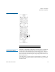
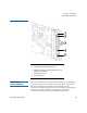
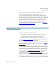
Figure 9 FC I/O Blade
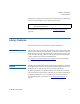
Each FC I/O blade is cooled by a fan blade that is installed next to the FC
I/O blade in the expansion module. For information on installing the fan
blade, see Adding, Removing, and Replacing the FC I/O Fan Blade
on
page 454.
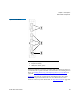
Figure 10
shows the FC I/O fan blade, including the LED. The single
amber LED represents health status. For more information on the
behavior of the FC I/O fan blade LED, see T
ape Drive LEDs on page 505.
1 FC ports to host(s)
2 FC ports to drive(s)
3 LEDs (blue, amber, green)