
User's Guide


Chapter 12 Installing, Removing, and Replacing
Cabling the Library
Scalar i500 User’s Guide 313
10 Connect the module-to-module cable from the control module to the
expansion module.
11 Connect an Ethernet cable to the Gigabit (GB) Ethernet port on the
Library Control Blade (LCB) for remote access to the library via the
Web client.
12 Connect a power cord to the outlet on the power supply on the rear of
the library.
There should always be a power cord connected to the power supply
on the control module. If redundant power supplies are used,
connect a power cord to each of the additional power supply outlets.
13 Power on the library.
a Turn on the rear power switch of each of the power supplies.
b Turn on the front power button.
c Power up the host system.
14 Verify communication with all devices on the bus.
15 Configure the library using the commands on the operator panel. See
configuration information in Configuring Your Library
on page 52.
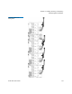
Recommended Library
Cabling for FC I/O Blades 12
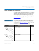
Fibre optic cables connect Fibre Channel tape drives to FC I/O blades and
FC I/O blades to a Storage Area Network (SAN) fabric or host. Correctly
managing these cables on the rear of the library can prevent damage to
the cables and Fibre Channel ports and ensure optimal data throughput.
Ideally, an installed tape drive should be cabled to a port on the nearest
FC I/O blade to eliminate the need to manage excessively long cables.
The nearest FC I/O blade is usually located in the same expansion
module as the tape drive.
You will need to provide fibre cables long enough to connect a host or a
SAN switch to a target port on an FC I/O blade.
Note: This section applies to libraries containing Fibre Channel tape
drives, which are connected to a host or a Fibre Channel
switch using an FC I/O blade. For tape drives that are directly
attached to a host or a SAN switch, follow standard fibre optic
cable handling best practices.