
User's Guide

Chapter 12 Installing, Removing, and Replacing
Cabling the Library
Scalar i500 User’s Guide 311
Required tools:
None
1 If your library is larger than 14U, install it in a rack. See Installing the
Library in a Rack on page 417 for instructions. The instructions
include procedures for removing and replacing tape drives.
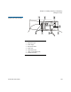
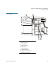
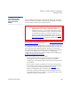
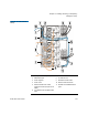
2 For each FC I/O blade installed in an expansion module, connect the
expansion module containing the FC I/O blade(s) to a port in the
Ethernet hub on the LCB:
a If the FC I/O blade is installed in the bottom bay of the expansion
module, connect one end of an Ethernet cable to the Ethernet port
labeled
LOWER in the lower right corner of the expansion
module. Connect the other end of the cable to a port in the
Ethernet hub on the LCB.
b If the FC I/O blade is installed in the upper bay of the expansion
module, connect one end of an Ethernet cable to the Ethernet port
labeled
UPPER in the lower right corner of the expansion module.
Connect the other end of the cable to a port in the Ethernet hub
on the LCB.
c Follow the instructions in Cable Management Guidelines
on
page 316 for best practices in routing the Ethernet cables.
Warning: All libraries taller than 14U must be installed in a rack
having a main protective earthing (grounding) terminal,
and power must be supplied via an industrial plug and
socket-outlet and/or an appliance coupler complying with
IEC 60309 (or an equivalent national standard) and having
a protective earth (ground) conductor with a cross
sectional area of at least 1.5 mm
2
(14 AWG).
To ensure proper airflow and access space, Allow 60 cm
(24 inches) in the front and back of the library.
Note: Pay attention to where the operator panel is positioned in the
rack for optimum usability.
Note: Without these Ethernet cables connected, the FC I/O
blades will not work.