P lan ning Guide Planning Guide Planning Guide Planning Guide i Quantum Scalar 2000 Library i Scalar 2000 6-00418-13 Rev A
Scalar i2000 Planning Guide, 6-00418-13 Rev A, August 2009, Made in USA. Quantum Corporation provides this publication “as is” without warranty of any kind, either express or implied, including but not limited to the implied warranties of merchantability or fitness for a particular purpose. Quantum Corporation may revise this publication from time to time without notice. COPYRIGHT STATEMENT Copyright 2009 by Quantum Corporation. All rights reserved.
Contents Chapter 1 About This Guide and Your Product 1 Product Safety Statements................................................................................ 1 Product Model Number.................................................................................... 2 Explanation of Symbols and Notes ................................................................. 2 Other Documents You Might Need ................................................................ 3 Getting More Information or Help.......
Chapter 3 System Specifications 30 Performance Specifications............................................................................. 30 Environmental Specifications......................................................................... 31 Electrical Specifications................................................................................... 31 Physical Specifications .................................................................................... 35 Module Foot Pad Positions.............
Chapter 1 1 About This Guide and Your Product This guide contains information necessary for site planning prior to the installation of the Scalar i2000. This guide is intended for anyone interested in learning about or anyone that needs to know how plan for the installation of the Scalar i2000. CAUTION Be sure to read all operating instructions in this manual and in the System, Safety, and Regulatory Information Guide before operating this product.
Chapter 1 About This Guide and Your Product Product Model Number bodily injury, damage to the equipment, or interference with other equipment. WARNING BEFORE POWERING ON OR USING THIS EQUIPMENT, READ THE SYSTEM, SAFETY, AND REGULATORY INFORMATION GUIDE. KEEP THE GUIDE FOR FUTURE REFERENCE. Product Model Number The Scalar i2000 model number is as follows: SCi2000 Explanation of Symbols and Notes The following symbols appear throughout this document to highlight important information.
Chapter 1 About This Guide and Your Product Other Documents You Might Need Note Indicates important information that helps you make better use of your system. Other Documents You Might Need The following documents are also available for this product. These documents can be found on the product CD or at www.quantum.com/ support.
Chapter 1 About This Guide and Your Product Getting More Information or Help Getting More Information or Help More information about this product is available on the Service and Support website at www.quantum.com/support. The Service and Support Website contains a collection of information, including answers to frequently asked questions (FAQs). You can also access software, firmware, and drivers through this site.
Chapter 2 2 Description The Scalar i2000 library automates the retrieval, storage, and control of cartridges. The cartridges are mounted and retrieved from tape drives using a robotic assembly that is driven by application software from the host without operator intervention. The library can be installed on a solid or a raised floor. The library has a standard 19-inch rack footprint and can be placed in a standard server rack space.
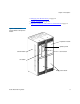
Chapter 2 Description • Managing Your Remote Library on page 24 • Capacity on Demand on page 28 • Magazine and Drive Location in the Control Module on page 16 Figure 1 Front View of a Control Module and Expansion Module expansion module operator panel control module touch screen I/E station access doors Scalar i2000 Planning Guide 6
Chapter 2 Description Control Module Control Module The control module contains the following components, as shown in figure 2 on page 8.
Chapter 2 Description Control Module Figure 2 Front and Back View of the Control Module front view magazines and cartridge slots back view I/O management unit I/E station drive clusters library management module power supplies picker Library Management Module 2 The library management module controls system hardware and enables external devices to perform configuration and obtain system status.
Chapter 2 Description Control Module Figure 3 Library Management Module Boards management control blade robotics control unit library motor drive Cartridge Accessor Scalar i2000 Planning Guide 2 The cartridge accessor moves cartridges between storage cells, tape drives, and the I/E station. A picker is used to get or put cartridges in a storage cell or a tape drive slot. The picker moves along an X and Y axis and can pivot 180o.
Chapter 2 Description Control Module Import/Export Station 2 I/E stations enable you to import and export cartridges without interrupting normal library operation. The I/E station is installed on the front of the control module or any of the seven expansion modules. See figure 1 on page 6 and figure 2 on page 8 to see the location of the I/E station. Each I/E station has a capacity of 24 LTO or 20 SDLT cartridges that are located in four removable magazines.
Chapter 2 Description Control Module Figure 4 Example of LTO Cartridge Insertion into a Magazine magazine barcode LTO cartridge LTO magazine cartridge barcode location See Mixed Media Support and Rules on page 13 for details about the use of drives and cartridges. See Barcode Requirements on page 58 for additional specification information. WORM Support 2 The Scalar i2000 library supports WORM (write once, read many) technology in LTO-3 and LTO-4 tape drives.
Chapter 2 Description Control Module Tape Drives 2 The tape drives are enclosed in a universal drive sled. You can hot swap and hot add all types of drives.
Chapter 2 Description Control Module Mixed Media Support and Rules 2 The library supports both LTO and SDLT cartridges and drives in the same configuration, providing you adhere to the following rules: • When purchasing a library with mixed media, the new orders must specify the base system technology (either LTO or SDLT) and the number of magazines, the number of drives, and the number of I/E magazines for each media type they need.
Chapter 2 Description Control Module • Magazines must be installed in the control module starting with back rack (drive side). Once the back rack (drive side) is full, you must then install magazines in the door side, starting with the top left corner. See figure 5 on page 14. • The secondary media type is installed beginning at storage slot 4,096 or the first media magazine. See figure 5 on page 14.
Chapter 2 Description Control Module Cartridge Magazines 2 The cartridge magazine is a storage assembly that installs on the drive side or door side of the control module or expansion module. It contains the cartridge slots and provides flexibility when adding storage cartridges to a module. There are two types of magazines, one for SDLT and another for LTO. Because the two magazines are the same size they can be mixed in the library.
Chapter 2 Description Control Module Figure 6 Magazine and Drive Location in the Control Module I/E station cartridge magazines drives or storage drive side Scalar i2000 Planning Guide door side 16
Chapter 2 Description Control Module Operator Panel 2 The operator panel is located on the front of the control module and consists of indicators and a touch screen (see figure 7). The buttons are for library control and power while the indicators provide library status.
Chapter 2 Description Control Module Figure 8 LMC title bar menu bar tool bar current library current activity data transfer statistics data mount statistics current time and date media slot usage configuration summary system status buttons For additional information on the touch screen and the LMC, refer to the Scalar i2000 User’s Guide.
Chapter 2 Description Expansion Modules Power System 2 The library supports single and redundant power configurations. The single configuration has a single AC line input and single DC power supply. The redundant configuration has dual AC line input and dual DC power supplies. You can hot swap a power supply if you have a redundant power supply. You can hot add a second power supply.
Chapter 2 Description Expansion Modules If an expansion module contains only cartridges, all power is derived from the control module. Note To ensure ethernet communication, control management blades (CMB) must be installed in each expansion module of a multi-module configuration. If the last expansion module does not contain FC I/O blades, a CMB is not necessary.
Chapter 2 Description I/O Management Unit I/O Management Unit The I/O management unit provides connectivity to a SAN fabric and the hosts, as shown in figure 10 on page 22. The I/O management unit houses six FC I/O blades which provide the FC connections for the 12 Fibre Channel drives in the module. The I/O management unit can be used to perform all tape drive and library host communication functions in a library that is attached to a SAN.
Chapter 2 Description I/O Management Unit Figure 10 I/O Management Unit control management blade FC I/O blades Scalar i2000 Planning Guide 22
Chapter 2 Description Host Attachment Host Attachment Requests issued from the host application result in cartridge movement in the library. The primary requests issued are for mounting and dismounting cartridges in and out of the tape drives and for importing and exporting cartridges in and out of the library. The library manages the physical location.
Chapter 2 Description Managing Your Remote Library The AMC also provides additional monitoring of a SAN-attached library over your existing network, including library subsystem health and status information and early fault notification to a management server via SNMP. For more information, refer to the Quantum Intelligent Libraries Basic SNMP Reference manual. Managing Your Remote Library Remote management of the Scalar i2000 is accomplished using the Library Management Console, (LMC).
Chapter 2 Description Managing Your Remote Library Figure 11 Multiple Workstations In the scenario shown in figure 11, Quantum highly recommends using virtual private network (VPN) software to control access to the Scalar i2000. VPNs offer authentication and encryption services to protect data transmissions and determine who can access a corporate network. By using VPN, the LMC client appears to be inside the firewall and have unrestricted access when communicating with the library.
Chapter 2 Description Managing Your Remote Library Scenario 2: Internal clients accessing a single library across an internal firewall 2 Another common customer configuration, is that a customer will want to allow multiple internal clients to manage a single Scalar i2000. For instance, as shown in figure 12 on page 26, network operation/data center staff providing monitoring services of specific resources.
Chapter 2 Description Managing Your Remote Library Scenario 3: Internal clients accessing multiple libraries across an internal firewall 2 Many customers use a layered system of firewalls to safeguard resources. In the scenario shown in figure 13, a customer may have multiple Scalar i2000s which need to be administered by internal staff (for instance data center / network operations staff) – with a firewall in between the administrators and libraries.
Chapter 2 Description Capacity on Demand Capacity on Demand If you purchased capacity on demand, the library is initially licensed for a default configuration of 100 SDLT or 102 LTO storage slots. The number of storage slots differs between media types because the library only supports full magazines for capacity on demand. The library’s license key must be enabled during installation to configure those parts of the library that are governed by additional licensing.
Chapter 2 Description Encryption and Quantum’s Encryption Key Manager Currently, the Scalar i2000 library supports encrypting LTO-4 tape media using IBM LTO-4 Fibre Channel drives only. All IBM LTO-4 FC drives are encryption-capable, but to use the Q-EKM software application, you must purchase a Q-EKM license and provide a server or servers on which to install Q-EKM.
Chapter 3 3 System Specifications This section provides performance, environmental, electrical, and physical specifications for modules in the library.
Chapter 3 System Specifications Environmental Specifications Environmental Specifications Table 2 lists the key environmental information for the library. Table 2 Environmental Specifications BTU/Heat Dissipation Temperature LTO: 59°F - 89.6°F (16°C - 32°C) SDLT: 64°F - 82°F (18°C - 28°C) Humidity Altitude Minimuma Maximumb 15 - 75% 10,000 ft .375 kwh 1280 BTU 4.3 kwh 14651 BTU c a.Configuration includes a control module with one drive. b.
Chapter 3 System Specifications Electrical Specifications The power cable length for each of these inputs is 14 feet (4.26 m). See table 3. For North America, the NEMA L6 - 30 power cord ships by default.
Chapter 3 System Specifications Electrical Specifications Table 4 Typical Module Power Consumption Module AMP @ 110 V AMP @ 220 V kW BTU/hr Minimum (1 drive) 3.4 1.7 .375 1280 Each additional drive 0.446 0.223 .050 167 Maximum (12 drives) 8.31 4.2 0.92 3121 I/O management unit 0.69 0.35 0.075 258 Each FC I/O blade 1.0 0.5 0.110 376 Maximum (12 drives, 1 I/O management unit, and 3 I/O blades) 12 6 1.32 4508 Minimum (no drives) 0 0 0 0 Each additional drive 0.446 0.
Chapter 3 System Specifications Electrical Specifications Table 5 Scalar i2000 Power Consumption Characteristics 230V / 50 Hz / 1 pH. Robot Operating Total Number Drives 12 12 12 12 6 3 1 0 Operational Drives 12 6 3 1 6 3 1 0 KW 0.77 0.76 0.75 0.74 0.54 0.48 0.35 0.31 KVA 0.82 0.8 0.79 0.79 0.58 0.52 0.38 0.35 KVAR (capacitive) 0.28 0.26 0.26 0.26 0.22 0.21 0.16 0.16 Power Factor 0.94 0.94 0.94 0.95 0.93 0.92 0.9 0.89 Crest Factor 1.85 1.85 1.82 1.
Chapter 3 System Specifications Physical Specifications Customer Library Connection Types and Speeds 3 Table 6 lists the library connection types and speeds. Table 6 Library Connections Types and Speeds Connectiona Connector Speed Fibre Channel on FC I/O Blade LC 2 gigabit/sec (6404) 4 gigabit/sec (7404) Fibre Channel on management control blade LC 1 gigabit/sec Ethernet on management control blade RJ45 10/100 Base-T SCSI-2 on management control blade 68-pin VHDCI Ultra-2 SCSI a.
Chapter 3 System Specifications Physical Specifications Table 7 Physical Specifications Height Width Depth Maximum Weight Distributed Load Point Load 24.3 in. 616.7 mm 38.3 in. 973.9 mm 899 lb 408.6 kg 139.1 lb/ft2 680.4 kg/m2 73.8 lb/in2 5.2 kg/cm2 38.3 in. 973.9 mm 885 lb 402.3 kg 140.9 lb/ft2 689.6 kg/m2 72.7 lb/in2 5.1 kg/cm2 777 lb 353.2 kg 123.7 lb/ft2 605.4 kg/m2 63.8 lb/in2 4.5 kg/cm2 Control Modulea 77.4 in. 1965.9 mm Expansion Modulesb 77.4 in. 1965.9 mm 23.6 in.
Chapter 3 System Specifications Physical Specifications Control Module and Expansion Module Pallet Specifications 3 Table 8 Pallet Dimensions Height Width Length 84 in. 2133.6 mm 41 in. 1041.4 mm 81 in. 2057.4 mm IEX Considerations 3 When adding expansion modules, you must consider IEX versions. 1 Take a snapshot of the library. 2 Find out what the IEX H/W Rev is for all the IEX board. 3 If any IEX H/W Rev is under 2, replace the IEX board.
Chapter 3 System Specifications Physical Specifications Figure 15 Configuration One Diagram Table 9 Configuration One Specifications Height Width Depth Maximum Weighta 77.4 in. 1965.9 mm 24.3 in. 616.7 mm 38.3 in. 973.9 mm 899 lb 408.6 kg Maximum Distributed Load Maximum Point Load 139.1 lb/ft2 680.4 kg/m2 73.8 lb/in.2 5.2 kg/cm2 a.Weight includes library fully loaded with drives, populated I/O management units, redundant power, and full media.
Chapter 3 System Specifications Physical Specifications Configuration Two 3 The second configuration consists of the control module and one expansion module. Options include: • Up to 12 additional LTO or SDLT drives (for a total of 24 drives) (LTO and SDLT can be mixed) • Redundant power supply • One additional I/E station • Additional storage (up to 456 LTO or 380 SDLT cartridges) The second configuration is shown in figure 16 on page 40. Physical specifications are listed in table 10 on page 40.
Chapter 3 System Specifications Physical Specifications Figure 16 Configuration Two Diagram Table 10 Configuration Two Specifications Height Width Depth Maximum Weighta 77.4 in. 1965.9 mm 47.9 in. 1215.7mm 38.3 in. 973.9 mm 1784 lb 810.9 kg Maximum Distributed Load Maximum Point Load 140 lb/ft2 684.9 kg/m2 73.3 lb/in2 5.2 kg/cm2 a.Weight includes library fully loaded with drives, populated I/O management units, redundant power, and full media.
Chapter 3 System Specifications Physical Specifications Configuration Three 3 The third configuration consists of one control module and two expansion modules. Options include: • Up to 12 additional LTO or SDLT drives (for a total of 36 drives) (LTO and SDLT can be mixed) • Redundant power supplies • Up to two additional I/E stations • Additional storage (up to 456 LTO or 380 SDLT cartridges) The third configuration is shown in figure 17 on page 42.
Chapter 3 System Specifications Physical Specifications Figure 17 Configuration Three Diagram Table 11 Configuration Three Specifications Height Width Depth Maximum Weighta 77.4 in. 1965.9 mm 71.4 in. 1814.7 mm 38.3 in. 973.9 mm 2669 lb 1213.2 kg Maximum Distributed Load Maximum Point Load 140.3 lb/ft2 686.4 kg/m2 73.1 lb/in2 5.1 kg/cm2 a.Weight includes library fully loaded with drives, populated I/O management units, redundant power, and full media.
Chapter 3 System Specifications Physical Specifications Configuration Four 3 The fourth configuration consists of the control module and three expansion modules. Options include: • Up to 12 additional LTO or SDLT drives (for a total of 48 drives) (LTO and SDLT can be mixed) • Redundant power supplies • Up to three additional I/E stations • Additional storage (up to 456 LTO or 380 SDLT cartridges) The fourth configuration is shown in figure 18 on page 44.
Chapter 3 System Specifications Physical Specifications Figure 18 Configuration Four Diagram Table 12 Configuration Four Specifications Height Width Depth Maximum Weighta 77.4 in. 1965.9 mm 95.0 in. 2413.7 mm 38.3 in. 973.9 mm 3554 lb 1615.5 kg Maximum Distributed Load Maximum Point Load 140.5 lb/ft2 687.2 kg/m2 73 lb/in2 5.1 kg/cm2 a.Weight includes library fully loaded with drives, populated I/O management units, redundant power, and full media.
Chapter 3 System Specifications Physical Specifications Configuration Five 3 The fifth configuration consists of the control module and four expansion modules. Options include: • Up to 12 additional LTO or SDLT drives (for a total of 60 drives) (LTO and SDLT can be mixed) • Redundant power supplies • Up to four additional I/E stations • Additional storage (up to 456 LTO or 380 SDLT cartridges) The fifth configuration is shown in figure 19 on page 46.
Chapter 3 System Specifications Physical Specifications Figure 19 Configuration Five Diagram Table 13 Configuration Five Specifications Height Width Depth Maximum Weighta 77.4 in. 1965.9 mm 118.6 in. 3012.7 mm 38.3 in. 973.9 mm 4331 lb 1968.6 kg Maximum Distributed Load Maximum Point Load 123.7 lb/ft2 605.4 kg/m2 63.8 lb/in2 4.5 kg/cm2 a.
Chapter 3 System Specifications Physical Specifications Configuration Six 3 The sixth configuration consists of the control module and five expansion modules. Options include: • Up to 12 additional LTO or SDLT drives (for a total of 72 drives) (LTO and SDLT can be mixed) • Redundant power supplies • Up to five additional I/E stations • Additional storage (up to 456 LTO or 380 SDLT cartridges) The sixth configuration is shown in figure 20 on page 48.
Chapter 3 System Specifications Physical Specifications Figure 20 Configuration Six Diagram Table 14 Configuration Six Specifications Height Width Depth Maximum Weighta 77.4 in. 1965.9 mm 142.2 in. 3611.7 mm 38.3 in. 973.9 mm 5108 lb 2321.8 kg Maximum Distributed Load Maximum Point Load 123.7 lb/ft2 605.4 kg/m2 63.8 lb/in2 4.5 kg/cm2 a.
Chapter 3 System Specifications Physical Specifications Configuration Seven 3 The seventh configuration consists of the control module and six expansion modules. Options include: • Up to 12 additional LTO or SDLT drives (for a total of 84 drives) (LTO and SDLT can be mixed) • Redundant power supplies • Up to six additional I/E stations • Additional storage (up to 456 LTO or 380 SDLT cartridges) The seventh configuration is shown in figure 21 on page 50.
Chapter 3 System Specifications Physical Specifications Figure 21 Configuration Seven Diagram Table 15 Configuration Seven Specifications Height Width Depth Maximum Weighta 77.4 in. 1965.9 mm 165.8 in. 4210.7 mm 38.3 in. 973.9 mm 5885 lb 2675 kg Maximum Distributed Load Maximum Point Load 123.7 lb/ft2 605.4 kg/m2 63.8 lb/in2 4.5 kg/cm2 a.
Chapter 3 System Specifications Physical Specifications Configuration Eight 3 The eighth configuration consists of the control module and seven expansion modules.The options available are: • Up to 12 additional LTO or SDLT drives (for a total of 96 drives) (LTO and SDLT can be mixed) • Redundant power supplies • Up to seven additional I/E stations • Additional storage (up to 456 LTO or 380 SDLT cartridges) The eighth configuration is shown in figure 22 on page 52.
Chapter 3 System Specifications Physical Specifications Figure 22 Configuration Eight Diagram Table 16 Configuration Eight Specifications Height Width Depth Maximum Weighta 77.4 in. 1965.9 mm 189.4 in. 4809.7 mm 38.3 in. 973.9 mm 6662 lb 3028.2 kg Maximum Distributed Load Maximum Point Load 123.7 lb/ft2 605.4 kg/m2 63.8 lb/in2 4.5 kg/cm2 a.
Chapter 3 System Specifications Module Foot Pad Positions Module Foot Pad Positions The library foot pad positions looking down from the top are shown in figure 23 on page 53. The foot pad positions are the same for the control module and expansion modules.
Chapter 3 System Specifications Module Floor Cutout Module Floor Cutout The foot pad positions are shown from underneath the library in figure 24 on page 54. The module floor cutouts are the same for the control module and expansion modules.
Chapter 3 System Specifications Scalar i2000 Seismic Bracing Figure 25 Module Floor Cutout (Front View) cutout Scalar i2000 Seismic Bracing For more information regarding seismic bracing solutions for the Scalar i2000, please request the Scalar i2000 Seismic Bracing Statement from your Quantum representative. Drive Requirements and Compatibility The library supports both FC and SCSI drives. Mixed media configurations are supported.
Chapter 3 System Specifications Drive Requirements and Compatibility 3 LTO Drives Although all four generations of LTO drives are supported in the library, the drives are not fully compatible (both read/write) as shown in table 17 on page 56.
Chapter 3 System Specifications Drive Requirements and Compatibility SDLT and DLT-S Drives 3 Four generations of SDLT and DLT-S cartridges are supported in the library, but the drives are not fully compatible (both read/write) as shown in table 20.
Chapter 3 System Specifications Barcode Requirements Table 19 SDLT and DLT Tape Drive Backward-Read Compatibility Transfer Rates Format (Continued) Data Cartridge type Capacity BRC Transfer Ratea DLT-S4 DLTtape S4 800 GB native 60 MB/s native 1600 GB compressed 120 MB/s compressed 80 GB 6.4 MB/s SDLT-VS160 DLTtape-VS1 a.The transfer rates shown are nominal based on 80% of actual native read transfer rate of uncompressed data. The DLT-S4 transfer rate shown is 2:1 compression ratio.
Chapter 3 System Specifications Barcode Requirements For SDLT I and SDLT II media barcodes, the library supports 14 characters for volume serial number plus a one-character media type identifier. For specific media type identifiers, see below. Table 20 SDLT and DLT-S Barcodes Data Cartridge type Format Media Type Identifier SDLT I SDLT-220 S1 SDLT I SDLT-320 S2 SDLT II SDLT-600 S3 DLT-S4 DLT-S4 S4 The barcode labels will provide the best results.
Chapter 4 4 Site Preparations This chapter provides a structure for the collection of all necessary information concerning the delivery site. Record all requested information in the forms provided or create additional sheets as needed.
Chapter 4 Site Preparations General Information General Information Place any additional information in Additional Comments on page 71.
Chapter 4 Site Preparations General Information Telephone Quantum sales rep.
Chapter 4 Site Preparations Physical Environment Physical Environment Place any additional information in Additional Comments on page 71.
Chapter 4 Site Preparations Access Conditions Fire protection Seismic bracing - If seismic bracing is being used, the pads must be onsite prior to installation. Type of power connector required Access Conditions Access to the library room (elevator, stairs, door widths, etc.
Chapter 4 Site Preparations Access Conditions Dimensions and location of the smallest door or opening Loading dock specifications (dock height, type of ramps, weather protection, etc.
Chapter 4 Site Preparations Access Conditions Where is the trailer location for staging? Availability of material handling equipment Location for uncrating Scalar i2000 Planning Guide 66
Chapter 4 Site Preparations Access Conditions Preferred time of day for unloading and moving materials Off hours/weekends accessibility for installation team Procedure for obtaining building passes Procedure for scheduling the elevator, loading dock Scalar i2000 Planning Guide 67
Chapter 4 Site Preparations Access Conditions Waste disposal considerations Bargaining unit considerations Other considerations Scalar i2000 Planning Guide 68
Chapter 4 Site Preparations Required Configuration Information Required Configuration Information The following is some of the information that will be needed during installation of the library. Place any additional information in Additional Comments on page 71. Library name: License string: IP address (internal) IP addresses of the two network time protocol (NTP) servers: Scalar i2000 Planning Guide 1. 2.
Chapter 4 Site Preparations Required Configuration Information SNMP server: SNMP account: SNMP sender address Subnet mask: Default gateway: SMTP server IP address: Note If your mail server requires a user name and password you can enable this on the library and enter these for e-mail authentication.
Chapter 4 Site Preparations SAN Readiness Operating system and version running off the remote servers that will connect to the library: SAN Readiness All servers or appliances intended to communicate with the Scalar i2000 robotic controller or tape drives must be already installed on the SAN before configuring the library for fiber channel SAN connectivity. Additionally, the World Wide Names (WWNs) of the associated fiber channel HBAs should be visible on the SAN.
Index Numerics D 49292 description functional 5 Heading1 Encryption and Quantum’s Encryption Key Manager 28 I I/E capacity 10 I/O management unit documents library interface 23 additional 3 Import/Export Station 10 latest versions 3 indicators 17 release notes 3 installation drives and blades 55 A intended use audience intended 1 statement 1 E electrical specifications 31 encryption 28 environmental specifications 31 C L library interface 23 component module Import/Export station 10 Co
Index shipping pallet specifications 36 P site preparation building passes 67 physical specifications 35 door dimensions 64 power loading dock 65 AC power cord 19 other considerations 68 power distribution unit 19 power supply 19 uncrate 66 specifications electrical 31 environmental 31 Q physical 35 Quantum 28 symbols and notes contacting 4 R explained 2 W release notes location 3 website customer service center 4 remote management library management console 23 S safety intended use 1