Scalar AIT 220 Library Installation and Operation
Copyright Copyright 1998 by Advanced Digital Information Corp (ADIC). All rights reserved. This item and the information contained herein are the property of ADIC. No part of this document may be reproduced, transmitted, transcribed, stored in a retrieval system, or translated into any language or computer language in any form or by any means, electronic, mechanical, magnetic, optical, chemical, manual, or otherwise, without the express written permission of ADIC, 11431 Willows Road N.E.
Revision History Revision Date Description A December 1998 Initial release for Scalar AIT 220 B June 1999 AIT-1, AIT-2 tape drives Revisions to This Manual This revision of Scalar AIT 220 Library Installation and Operation (B) contains the following changes and enhancements: • Added information about Scalar AIT 220’s support for AIT-1 & AIT-2 Tape Drives.
Product Warranty Caution The ADIC Scalar AIT 220 Library is warranted to be free from defects in materials, parts, and workmanship and will conform to the current product specification upon delivery. For the specific details of your warranty, refer to your sales contract or contact the company from which the library was purchased. The warranty for the library shall not apply to failures of any unit when: • The library is repaired by anyone other than the Manufacturer's personnel or approved agent.
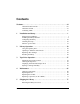
&RQWHQWV Welcome. . . . . . . . . . . . . . . . . . . . . . . . . . . . . . . . . . . . . . . . . . . . . . . . . . . . . . . vii About the Scalar AIT 220 . . . . . . . . . . . . . . . . . . . . . . . . . . . . . . . . . . . . . . viii About this manual . . . . . . . . . . . . . . . . . . . . . . . . . . . . . . . . . . . . . . . . . . . . . xii Contacting ADIC. . . . . . . . . . . . . . . . . . . . . . . . . . . . . . . . . . . . . . . . . . . . . . xv 1 Installation and Setup. . . . . . . . . . . . . .
Packing the library . . . . . . . . . . . . . . . . . . . . . . . . . . . . . . . . . . . . . . . . . . . . . 78 6 Advanced Operation. . . . . . . . . . . . . . . . . . . . . . . . . . . . . . . . . . . . . . . . 89 Using elements . . . . . . . . . . . . . . . . . . . . . . . . . . . . . . . . . . . . . . . . . . . . . . . . 89 Viewing library information . . . . . . . . . . . . . . . . . . . . . . . . . . . . . . . . . . . . . . 92 Performing diagnostics. . . . . . . . . . . . . . . . . . . . . . . . . .
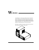
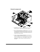
W HOFRPH Congratulations on selecting the ADIC Scalar AIT 220 Library. Your new library provides unattended data storage, archiving, backup, and retrieval for mid-range and high-end workstations, servers, and networks. The robotic cartridge handling mechanism (CHM) automatically moves cartridges between tape drives and storage slots, while the tape drives read and write data. The library is available in standalone (vertical) and rack-mount (horizontal) models, as shown in the figure.
$ERXW WKH 6FDODU $,7 The Scalar AIT 220 includes two data cartridge magazines and either one or two 3.5” form factor Sony AIT tape drives. It can operate as three SCSI devices on up to three SCSI buses. When the library is is equipped with AIT-1 drives, the library is a differential SCSI-2 device and the drives are differential Fast/Wide SCSI-2 devices.
The Sony SDX1-25C, SDX1-35C, SDX2-36C, and SDX2-50C data cartridges support the Advanced Intelligent Tape format. The cartridges use a new recording format, Adaptive Lossless Data Compression (ALDC), Memory In Cassette (MIC) technology capabilities and use Sony’s AME media, which incorporates dual cobalt magnetic layers, the absence of binder material to prevent tape head contamination and a super-durable “diamond-like carbon” protective coating for extreme durability.
,QWHUQDO FRPSRQHQWV S Tape drives. The library can include one or two AIT-1 or AIT-2 tape drives, which are housed in drive carriers. S Data cartridge magazine(s) and fixed slot. The Scalar AIT 220 includes two removable 10-tape magazines on a rotor. The fixed slot allows you to store an AIT cleaning cartridge or an additional AIT data cartridge. S CHM (cartridge handling mechanism). The CHM is the robotic assembly that moves cartridges between the storage locations and the tape drives.
%DFN SDQHO FRPSRQHQWV S Fan and power entry module. The fan reduces the library's operating temperature. The power entry module includes the AC power connector, power switch, and fuse drawer. S Remote hardware reset port. This port allows you to connect a remote reset cable for remote resets. S 9-pin and 25-pin serial ports. Two serial ports allow you to connect a serial cable and terminal for diagnostics. S SCSI connectors.
$ERXW WKLV PDQXDO Use this manual to install, configure, operate, maintain, and diagnose problems with the Scalar AIT 220 and its enclosed AIT tape drives. It includes the following chapters: S Chapter 1 explains how to install and set up the library. S Chapter 2 describes how to configure the library. S Chapter 3 describes how to check your setup. S Chapter 4 describes basic library operations. S Chapter 5 describes basic tape drive operations. S Chapter 6 describes basic maintenance procedures.
&RQYHQWLRQV XVHG LQ WKLV PDQXDO This manual uses the following conventions: >(QWHU@ Boxed text indicates keys on the library's operator panel keyboard. 1RWH Notes provide hints or suggestions about the topic or procedure being discussed.
5HODWHG SXEOLFDWLRQV For information about these libraries, the tape drives, and the standards used by these libraries, refer to the following publications available from ADIC.
&RQWDFWLQJ $',& )RU WHFKQLFDO VXSSRUW $',& 7HFKQLFDO $VVLVWDQFH &HQWHU $7$& 86 H PDLO VXSSRUW#DGLF FRP :RUOG :LGH :HE KWWS ZZZ DGLF FRP %XOOHWLQ %RDUG %%6 ,QWHUQDWLRQDO &RQQHFW DW XS WR EDXG ZLWK GDWD ELWV VWRS ELW DQG QR SDULW\ 7XUQ RQ KDUGZDUH 576 &76 IORZ FRQWURO 7R RUGHU VXSSOLHV DQG DFFHVVRULHV $',& 6DOHV ID[ 7R UHWXUQ HTXLSPHQW IRU VHUYLFH $',& 7HFKQLFDO $VVLVWDQFH
1RWHV [YL 6FDODU $,7
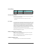
1 ,QVWDOODWLRQ DQG 6HWXS This chapter describes how to install and set up your library. Preparing for installation This section provides step-by-step instructions for preparing the library. You can use the table below as a checklist. ✔ Step Description 1 Unpack the library. 2 Obtain accessories and equipment. 3 Prepare the host computer. 4 Prepare the library for installation. Step 1 – Unpack the library Complete the unpacking steps printed on the box.
&KDSWHU Step 2 – Obtain accessories and equipment Make certain you have all the accessories and equipment for library operation, as indicated in the table below. Many of these items are included in the library accessories box, shipped in a separate box at the top of the carton. Required accessories and equipment Power cord Included with the library. (Page 135 provides power cord specifications for other voltages and international use.) Two keys for front door Included with the library.
,QVWDOODWLRQ DQG 6HWXS Step 3 – Prepare the host computer Make certain the SCSI host bus adapter card installed in the computer and the application software are compatible with the Scalar AIT 220. You can obtain software compatibility information about ADIC products from ADIC’s internet site (http://www.adic.com). Note: If your application only supports a single AIT tape drive, you can run the library in one of the sequential modes (see page 46 and page 153).
&KDSWHU Installing the library hardware This section provides step-by-step instructions for installing the library hardware. You can use the table below as a checklist. ✔ Step Description 1 Install the library into a rack, if you have a rack-mount model. 2 Unlock and open the front door. 3 Remove the packing foam. 4 Prepare and install cartridges. 5 Close and lock the door. 6 Connect the library to the SCSI bus. 7 Connect the power cord. 8 Power on the library.
,QVWDOODWLRQ DQG 6HWXS Step 1 – Install the library into a rack If you have a rack-mount library, follow these instructions to install the library into a standard EIA 19-inch rack. WARNING! Depending on the number of drives installed, the rack-mount library weighs 50 – 70 pounds (27.2 – 31.8 kg); the standalone library weighs 70 – 90 pounds (31.8 – 40.9 kg). At least 2 people are needed to move or lift the library. Most of the weight is toward the back of the library.
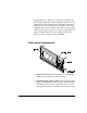
&KDSWHU To install the library into a rack: 1. Locate the slide rail assembly attached to each side of the library chassis, as shown in the figure. 2. Slide the rack-slide rail toward the rear of the library, as shown in the figure. Press the spring clips to remove the rack-slide rail from the chassis-slide rail.
,QVWDOODWLRQ DQG 6HWXS 3. Locate the mounting holes on the rack where you want to install the library. Allow 1½ inches (3.8 cm) minimum clearance below the bottom mounting hole. Note: If the rack does not have threaded holes, attach the clip nuts provided with the library over the mounting holes, as shown in the figure.
&KDSWHU 4. Orient the rack-slide rails so that the metal stop is towards the back of the cabinet, as shown in the figure. If the rails are not long enough to reach the back of the cabinet, use a T-15 TORX driver to loosen the nuts on the rails. Extend the rails to the desired length and tighten the nuts.
,QVWDOODWLRQ DQG 6HWXS 5. Using a T-25 TORX driver and four screws per rail, attach (but do not tighten) the rack slide rails to the mounting holes on the rack, as shown in the figure on page 7. 6. Adjust the distance between the rail brackets on each side of the cabinet to 17 5/8 inches (44.75 cm). Measure both the front and back. 7. Use a T-25 TORX screwdriver to tighten the screws to 12.0 inch-pounds (13.8 kg-cm) of torque.
&KDSWHU 8. Using two people to lift it, slide the library into the rack by inserting the chassis slide rails into the rack slide rails, as shown in the figure. Press the spring clips while pushing the library firmly into the rack. When the library is seated properly, you will hear the latch engage.
,QVWDOODWLRQ DQG 6HWXS Step 2 – Unlock and open the front door To open the front door, insert the key from your accessory kit into the lock, push in, and turn the key one-quarter turn to the right. Pull open the door.
&KDSWHU Step 3 – Remove the packing foam To remove the two foam packing pieces: 1. From inside the door, remove the first foam packing piece (rack-mount model shown below). 2. To remove the second foam packing piece, you must first move the cartridge handling mechanism (CHM) out and away from the magazine, as described on the next page. ➤ Important The CHM contains a bar code scanner. Do not touch the lens when you move the CHM. Smudges on the lens can cause scan errors. 3.
,QVWDOODWLRQ DQG 6HWXS Rack-mount model: ➊ Pull firmly on the upper portion of the CHM to slide it back (toward you). Do not pull on the CHM base. ➋ Push against the CHM base, sliding it firmly to the right or left. Standalone model: ➊ Pull firmly on the upper portion of the CHM to slide it back (toward you). Do not pull on the CHM base. ➋ Push against the CHM base, sliding it firmly to the top or bottom.
&KDSWHU Step 4 – Prepare and install cartridges Four types of AIT data cartridges are available: SDX1-25C, SDX1-35C, SDX2-36C and SDX2-50C. The SDX1-25C and SDX2-36C are 170 meters in length, while the SDX1-35C and SDX2-50C are 230 meters in length and all use Sony’s Advanced-Metal Evaporated (AME) tape.
,QVWDOODWLRQ DQG 6HWXS To prepare and install cartridges: Your library is equipped with a bar code scanner. You can affix bar code labels to the cartridges. To do this, position the label using the ridge on the cartridge for guidance. Make sure you orient the label correctly, as shown in the following illustration. ➤ Important If you remove a bar code label from a data cartridge without replacing it, make sure you clean the label area thoroughly.
&KDSWHU 4. Make sure the write-protect switches on the cartridges are set correctly, as shown in the following figure. You can use a ball-point pen or similar instrument to set the write-protect switch. If the orange tab fills the window, the cartridge is write-protected.
,QVWDOODWLRQ DQG 6HWXS 5. Remove the cartridge magazine (shown in the following figure). For rack-mount models, pull it out first from the right, then the left; for standalone models, pull it out first from the top, and then bottom. Access the back magazine by turning the rotor manually. CAUTION Make sure the CHM and its cabling are safely out of the way before you remove or install a cartridge magazine. If the CHM is blocking the magazine, move it by following the instructions on page 13.
&KDSWHU 6. Place the magazine on its feet with the single mounting guide toward the right. Position each cartridge so that the bar code label is on top and the write-protect switch is toward the front. Insert the cartridge into the magazine slot. Note: Very little force is needed to install a data cartridge. If it does not snap into place easily or if it protrudes further than the magazine’s center rib, check the orientation of the cartridge. 7. To re-install the magazine, follow the instructions below.
,QVWDOODWLRQ DQG 6HWXS 8. The library contains one fixed cartridge slot for a cleaning cartridge or an additional data cartridge. If desired, install a cleaning cartridge in the fixed cartridge slot, as shown on the following page. ➤ Important Use only a Sony SDX-TCL cleaning cartridge.
&KDSWHU Rack-mount model: Position the cleaning cartridge so that the window showing the tape reels is to the right and snap the cartridge into place. Standalone model: Position the cleaning cartridge so that the window showing the tape reels is to the top and snap the cartridge into place.
,QVWDOODWLRQ DQG 6HWXS Step 5 – Close and lock the door Close the door and turn the key a quarter-turn to the left. Step 6 – Connect the library to the SCSI bus This section provides general guidelines for connecting the library to the SCSI bus. The library consists of three SCSI devices: the library itself and the two tape drives. If a drive blank is installed, the library consists of two SCSI devices (the drive blank is not addressable). Before you begin 1.
&KDSWHU 5. For each device that terminates the bus (either the library or one of the tape drives), install a terminator on one of the connectors for that device. Connecting the Scalar AIT 220 The Scalar AIT 220 can operate on one, two, or three SCSI buses. The library, Drive 1, and Drive 2 can operate on separate SCSI buses or on the same SCSI bus. 1. Connect the library to the SCSI bus, using the connector assignments shown in the following figure.
,QVWDOODWLRQ DQG 6HWXS 2. If you are connecting the library and two tape drives to one or two SCSI buses, install a jumper (or jumpers) over the connectors between devices, as shown in the example.
&KDSWHU 3. For each device that terminates the bus (either the library or one of the tape drives), install a terminator on one of the connectors for that device. The example below shows a Scalar AIT 220 connected to three SCSI buses. All the buses are terminated.
,QVWDOODWLRQ DQG 6HWXS Step 7 – Connect the power cord ➤ Important The power cord shipped with the library is a 120 VAC three-conductor power cord for use in the United States and Canada. If you are planning to use an input voltage other than 120 volts AC or if you plan to use the library outside of the United States or Canada, you must supply your own power cord. Refer to page 135 for more information. 1. Make sure that the power switch on the back of the library is off (the 0 is pressed).
&KDSWHU 2. Connect the female end of the power cord to the power connector on the back of the library. 3. Plug the male end of the power cord into the power source. Note: The library has autoranging voltage selection, so you do not need to change the voltage setting. Step 8 – Power on the library 1. Make certain the library's door is closed and locked. 2. Turn on the host computer system.
,QVWDOODWLRQ DQG 6HWXS If problems occur . . . If the library does not power on as described: Check the following: S Is the power switch on (1 is pressed)? S Is the power cord inserted correctly? S Is the library door closed and locked? S Is the SCSI bus terminated? S Is the SCSI cable connected to the library and host computer? S Is the host computer system turned on? For additional troubleshooting tips, see “Problems with library installation” on page 128.
&KDSWHU Configuring the library Configuration steps include: S S S S Displaying the Configuration Menu Setting SCSI IDs Setting LCD security (optional) Setting other configuration options (if necessary) To change options, you will use the operator panel (LCD and keypad) on the front of the library, as shown in the figure. If desired, you can tilt the LCD for easier viewing.
,QVWDOODWLRQ DQG 6HWXS Step 1 – Display the Configuration Menu To display the Configuration Menu: 1. Access the Main Menu by pressing >(VFDSH@ on the keypad. The Main Menu is shown. →M a i n S c r e e n I n t e r C o n f f a c e M e n u i g u r a t i o n M a i n t e n a n c e M e n u M e n u ↓ 2. Press > @ to scroll down to Configuration Menu. Then press >(QWHU@.
&KDSWHU During library configuration, use the operator keys for the following functions: To select an item from a menu: Press > @ or > @ to scroll up and down through the items. When the screen arrow (→) points to the desired item, press >(QWHU@. To move the screen arrow left and right, or toggle some options: Press > @ or > @. To return to a previous screen Press >(VFDSH@.
,QVWDOODWLRQ DQG 6HWXS To view or change the SCSI IDs: 1. From the Configuration Menu, select Set SCSI IDs. The following screen appears: S C S I D 2 D 1 I D s : 3 2 L I B 1 ¦ ↓ → 2. To set the SCSI ID for Drive 2 (farthest from the magazine), press > @ or > @ until the screen displays the correct SCSI ID. 3. Press > @ to move the screen arrows to Drive 1. 4. To set the SCSI ID for Drive 1 (closest to the magazine), press > @ or > @ until the screen displays the correct SCSI ID. 5.
&KDSWHU Step 3 – Set security The Security option allows you to prevent unauthorized personnel from disrupting the operation of the library.
,QVWDOODWLRQ DQG 6HWXS Whichever method is used to enable security (operator panel or SCSI) must also be used to disable security. That is, if you enable security from the operator panel, you must disable it from the operator panel. If security is enabled by the application (SCSI), it must be disabled by the application. Note: To determine if security has been set by your application, look at the SCSI Mode Parameters screen (see page 93). Security remains in effect across resets.
&KDSWHU Disabling security from the operator panel 1. From the Configuration Menu, select Set Security Off. The following screen appears: S e t S e c u r E n t e r i t y P a s s w o r d f : 0 0 0 ↑ T h e n P r e s s O f E n t e r → Note: If the menu displays Set Security On, the LCD security function is disabled. However, security may have been enabled by your application using a SCSI command. If so, it must be disabled by your application. Refer to your software documentation. 2.
,QVWDOODWLRQ DQG 6HWXS Step 4 – Set other configuration options The Configuration Menu contains some other configuration options for the library, as described in the table below. If desired, you can check these settings and change them. Configuration options SCSI Parity* Allows you to enable parity checking for the library (if the SCSI adapter card connected to the library supports it). When enabled, the library checks all data on the SCSI bus for parity. This remains in effect across power cycles.
&KDSWHU * Parity checking for the library can also be enabled by the application software using the SCSI command, MODE SELECT. The method used last to set parity checking (LCD or SCSI command) has precedence. Parity checking for tape drives is set separately. Checking the setup After installing the hardware and software, check the setup by performing some exercises on the library, as described below.
,QVWDOODWLRQ DQG 6HWXS If problems occur . . . If the library and tape drive are not operating as expected: See Chapter 7 for troubleshooting information. If there is an error code displayed on the LCD: See Appendix J for a list of error codes and corrective actions. If you cannot solve the problem yourself: Contact your service provider or ADIC. Where to go from here Before you begin library operations, check the following: • A cartridge magazine is installed.
&KDSWHU 1RWHV 6FDODU $,7
/LEUDU\ 2SHUDWLRQ Once the library and application software are installed and configured, you can automatically perform backup and restore operations using the application software. You do not need to intervene in the cartridge processing during normal library operations.
&KDSWHU 8VLQJ WKH RSHUDWRU SDQHO The library includes a four-line LCD and keypad, called the operator panel, which allows you to interactively control library operations. Using the operator panel, you can set library options, check operating statistics, and diagnose errors. If desired, you can tilt the LCD for easier viewing. 0DLQ 6FUHHQ The Main Screen appears when you apply power to the library. The first and second lines on the Main Screen identify the product name, firmware version, and time.
/LEUDU\ 2SHUDWLRQ An example of the Main Screen with a status message is shown below. A D I C V E R 2 2 0 3 . 1 . 1 3 1 2 : 1 5 : 3 7 S t a t u s : M o v e 1 - D R I V E P i c k i n g F r o m S l o t 1 1RWH The exact wording of the Main Screen may be different on your screen. (UURU FRGHV If a hardware error occurs, an error code will appear automatically on the third and fourth lines of the Main Screen. You must correct the error before operation can continue.
&KDSWHU 0DLQ 0HQX To access the Main Menu, press >(VFDSH@ from the Main Screen. The Main Menu is shown below: →M a i n S c r e e n I n t e r C o n f f a c e i g u r a t M e n u i o n M a i n t e n a n c e M e n u M e n u ↓ The selections on the Main Menu are described in the following table. The menu structure is shown on the next page.
/LEUDU\ 2SHUDWLRQ ,QVWDOODWLRQ DQG 2SHUDWLRQ
&KDSWHU 2SHUDWRU NH\V Use the keys on the operator panel to perform the following actions: > @ > @ > @ > @ >+HOS@ >(VFDSH@ 6FUROOV WKH VFUHHQ DUURZ → XS RU GRZQ 7KH VFUHHQ DUURZ SRLQWV WR WKH FXUUHQW VHOHFWLRQ ,Q VRPH VFUHHQV PRYHV WKH VFUHHQ DUURZ OHIW RU ULJKW 2Q VRPH PHQX VHOHFWLRQV WRJJOHV DQ RSWLRQ RQ RU RII 'LVSOD\V WKH +HOS VFUHHQ 7R H[LW +HOS SUHVV [Escape] 5HWXUQV WR WKH SUHYLRXV PHQX RU VFUHHQ FDQFHOV DQ RSHUDWLRQ ZLWKRXW VDYLQJ FKDQJHV RU LI WKH 0DLQ 6FUHHQ LV GLVSOD\H
/LEUDU\ 2SHUDWLRQ 2SHUDWLQJ LQ GLIIHUHQW FRQWURO PRGHV To determine which interface will control CHM motion, you can set the library to one of the following control modes: S S S S S S SCSI Interface Sequential 1 Sequential 2 Dual Sequential LCD Interface 25/9-Pin These control modes allow you to operate the library with the application software (SCSI Interface), operate the library as a sequential stacker device (Sequential 1, Sequential 2, Dual Sequential), or perform diagnostic functions on the library
&KDSWHU &RQWURO PRGH GHVFULSWLRQV 6&6, ,QWHUIDFH PRGH If you want the application software to control library operations, you must set the library to SCSI Interface mode. In this standard operating mode, the application software controls the motion of the CHM by issuing SCSI commands across the SCSI bus. 1RWH The application software can issue commands to the library regardless of the control mode. However, the library must be in SCSI Interface mode for the application software to control CHM motion.
/LEUDU\ 2SHUDWLRQ /&' ,QWHUIDFH PRGH If you want to perform any operations from the operator panel that involve moving the CHM, you need to set the library to LCD Interface mode. All of these operations, such as cleaning the tape drives and performing diagnostics, are included under the Maintenance Menu. 1RWH LCD Interface mode is required only when you want to control the motions of the CHM. For example, you do not need to switch control modes to access the menus.
&KDSWHU From the Interface Menu, select Control Mode Menu. The following screen appears: → L C D I n t e r * S C S I f a c e I n t e r f a c e S e q u e n t i a l 1 S e q u e n t i a l 2 ↓ 1RWH The Sequential 2 option does not appear in this menu if you have a drive blank installed. The Dual Sequential option does not appear if you are operating with only one tape drive. Select the desired mode. The current control mode is indicated with an asterisk (*).
/LEUDU\ 2SHUDWLRQ 5HSODFLQJ GDWD FDUWULGJHV This section describes how to: S S S S Select the appropriate data cartridges for your tape drive Open the library door to access the cartridges Replace a single cartridge or a cartridge magazine Store cartridges outside the library 6HOHFWLQJ GDWD FDUWULGJHV ADIC strongly recommends that you use Sony® data-grade media with your AIT tape drives. Sony media meets specifications that are the most stringent in the industry.
&KDSWHU 2SHQLQJ WKH OLEUDU\ GRRU To access the cartridges, you must first open the library door.
/LEUDU\ 2SHUDWLRQ When the CHM finishes the current operation and moves to the park position, the door's interlock mechanism releases. Open the door. &$87,21 'R QRW IRUFH WKH GRRU RSHQ 7KH GRRU V LQWHUORFN PHFKDQLVP PD\ EH SUHYHQWHG IURP UHOHDVLQJ E\ /&' VHFXULW\ RU E\ WKH DSSOLFDWLRQ VRIWZDUH 5HSODFLQJ D VLQJOH FDUWULGJH To replace a single cartridge: Remove the cartridge by pulling it straight out from its slot in the cartridge magazine.
&KDSWHU Close and lock the library's door. 5HSODFLQJ WKH FDUWULGJH PDJD]LQH Open the library door, as described on page 50. For rack-mount models, remove the front cartridge magazine by pulling it out first from the right, then the left. For standalone models, pull it out first from the top, then the bottom.
/LEUDU\ 2SHUDWLRQ You can access the back magazine by turning the rotor manually. The rotor is shown below. If desired, replace the cartridges (described on page 51).
&KDSWHU Position the magazine so that the single mounting guide on the magazine is aligned with the roller on the mounting plate, as shown in the figure. For rack-mount models, clip the magazine onto the left side and snap it into place by pressing on the right side. For standalone models, clip the magazine onto the bottom and snap it into place by pressing on the top. Close and lock the door.
/LEUDU\ 2SHUDWLRQ 6WRULQJ FDUWULGJHV To maximize the shelf life of your tapes and ensure data integrity, follow these guidelines when storing cartridges: S Store cartridges in a suitable environment. Follow the specifications for storage temperature and other environmental requirements, as described on the cartridge packaging. Do not allow the temperature and humidity in the storage environment to fluctuate. S Keep the storage location as free of airborne particulates as possible.
&KDSWHU 5HVHWWLQJ WKH OLEUDU\ If the library has encountered an error and is still not operating after you have tried the corrective action for the error, you may need to reset the library. A reset causes the library and the tape drives to perform their power-on self tests. Unless configured otherwise, tape drives will rewind the tape after a reset, but will not eject the data cartridge.
7DSH 'ULYH 2SHUDWLRQ The application software automatically controls the tape drives to perform backup and restore operations.
&KDSWHU 0RQLWRULQJ WKH WDSH GULYH /('V The SDX-300C and SDX-500C tape drive use their three front panel LEDs to report the current status/operation of the drive. The following table shows the possible states of the three LEDs and the conditions they indicate.
7DSH 'ULYH 2SHUDWLRQ &OHDQLQJ WKH WDSH GULYHV You should clean a tape drive whenever the library displays “Drive needs cleaning” on the Main Screen of the LCD or whenever your application software notifies you. (Not all software applications display cleaning requirements.) Regular cleaning helps ensure that the tape drives function reliably. 1RWH Some applications monitor the tape drives’ cleaning needs and automatically insert the cleaning cartridge in the drive whenever it needs cleaning.
&KDSWHU Make certain a cleaning cartridge is installed in the fixed cartridge slot. (If the fixed slot contains a data cartridge and you follow these steps, you will have to manually eject the data cartridge from the tape drive.) If security has been enabled, disable it (see page 34). Switch to LCD Interface mode (see page 46). From the Main Menu, select Maintenance Menu. Then select Clean Drives Menu.
7DSH 'ULYH 2SHUDWLRQ Confirm that the cleaning was done by looking at the Status LED on the front of the drive. The Status LED should be off. If the LED is still on, replace the cleaning cartridge and clean the tape drive again. If the LED is still on after the second cleaning, there may be a problem with the tape drive.
&KDSWHU From the Main Menu, select Library Info Menu. Then select Drive Info Menu. The following screen appears: →D r i v e D r i v e 1 S t a t u s 2 S t a t u s ↓ Press > @ or > @ to select the desired tape drive and press >(QWHU@. A Drive Status screen appears, similar to the following: D R I V E 1 S T A T U S : T y p e A I T P r e s e n t 1 A c c e s s i b l e 1 ↓ The following table describes the information in the Drive Status screen.
7DSH 'ULYH 2SHUDWLRQ 'ULYH 6WDWXV VFUHHQ $FFHVVLEOH ,QGLFDWHV WKH DFFHVVLELOLW\ RI WKH WDSH GULYH WR WKH &+0 ² $ FDUWULGJH LV ORDGHG LQ WKH WDSH GULYH RU WKH WDSH GULYH V VWDWXV LV XQNQRZQ ² $ FDUWULGJH LV SURWUXGLQJ IURP WKH WDSH GULYH RU WKH GULYH LV HPSW\ &OHDQ ² 7KH WDSH GULYH LV FOHDQ ² 7KH WDSH GULYH QHHGV WR EH FOHDQHG RU WKH FOHDQLQJ WDSH LV XVHG XS :DUQLQJ 1RW FXUUHQWO\ XVHG 2FFXSLHG ² 7KHUH LV QR FDUWULGJH ORDGHG LQ WKH WDSH GULYH ² 7KHUH LV FXUUHQWO\ D FDUWULGJH OR
&KDSWHU BUSY TAPE STATUS EJECT BUTTON 6FDODU $,7
0DLQWHQDQFH This chapter describes the following: S S S S Cleaning requirements for the library Replacing the fuse Replacing the air filter Replacing the tape drives &$87,21 8QOHVV \RX KDYH D VHOI PDLQWHQDQFH FRQWUDFW ZLWK $',& GR QRW DWWHPSW WR UHSODFH DQ\ FRPSRQHQWV LQ WKH OLEUDU\ RWKHU WKDQ WKH WDSH GULYHV IXVH DQG DLU ILOWHU ,I \RX GR VR \RX ZLOO YRLG \RXU ZDUUDQW\ ,QVWDOODWLRQ DQG 2SHUDWLRQ
&KDSWHU &OHDQLQJ UHTXLUHPHQWV The only library components that should be cleaned are the tape drives and the window in the door. Instructions for cleaning the tape drives are provided on page 59. &$87,21 7KH OLEUDU\ V LQWHUQDO FRPSRQHQWV DUH OXEULFDWHG DW WKH IDFWRU\ DQG VKRXOG QRW EH FOHDQHG RU UHOXEULFDWHG To protect the internal components from dust, keep the library door closed and locked.
0DLQWHQDQFH 5HSODFLQJ WKH IXVH The library uses a 2.5 amp, 250-volt fuse, which is located in the fuse drawer at the back of the library next to the power cord connector. An extra fuse is provided in the fuse drawer. To order additional fuses, see page xv. &$87,21 :KHQ UHSODFLQJ WKH OLEUDU\ V IXVH XVH RQO\ WKH VDPH W\SH DQG UDWLQJ RI IXVH To replace the library's fuse: Turn off the library and remove the power cord. .
&KDSWHU Pull the blown fuse out of the fuse slot. Use the screwdriver to push the spare fuse box out of the fuse drawer. Remove the spare fuse and place it in the fuse slot. Insert the fuse drawer into the back panel. Push in until you hear it snap into place. If desired, order another spare fuse for the fuse drawer.
0DLQWHQDQFH 5HSODFLQJ WKH DLU ILOWHU The library includes an air filter, located behind the door. The air filter should be replaced once a year (or more frequently if the library is operating in a dirty environment). To order replacement filters, see page xv.
&KDSWHU Position the metal cover over the filter. Using a T-15 TORX bit, replace the three screws that secure the metal cover inside the front panel.
0DLQWHQDQFH 5HSODFLQJ D WDSH GULYH RU GULYH EODQN ³ ,PSRUWDQW 'R QRW PL[ GLIIHUHQW 6&6, FRQILJXUDWLRQV ZLWKLQ WKH VDPH OLEUDU\ Replacing a tape drive (or drive blank) involves the following steps: 6WHS 'HVFULSWLRQ 3UHSDUH IRU WKH UHSODFHPHQW SURFHGXUH 5HPRYH WKH WDSH GULYH ,QVWDOO WKH WDSH GULYH 5HVXPH OLEUDU\ RSHUDWLRQV 1RWH When you order a new tape drive for the library, the tape drive will be shipped to you in the drive carrier.
&KDSWHU 6WHS ² 3UHSDUH IRU UHSODFHPHQW Obtain a flat blade screwdriver. (Some models may require a #1 Phillips screwdriver.) Ensure that the environment is free of conditions that could cause electrostatic discharge (ESD). If possible, use an antistatic mat and grounded static protection wristband during installation. If a mat and wristband are not available, touch a known grounded surface, such as the computer's metal chassis. Unlock and open the library's door (see page 50).
0DLQWHQDQFH 6WHS ² 5HPRYH WKH WDSH GULYH To remove the tape drive: Using a flat blade screwdriver, loosen the two captive screws on each side of the faceplate. (Some models may require a #1 Phillips screwdriver.
&KDSWHU Using your finger, pull out the lever on the faceplate. The figures on page 75 show the location of the lever. &$87,21 'R QRW SXOO RXW WKH OHYHU ZLWKRXW ILUVW ORRVHQLQJ WKH VFUHZV Pull the tape drive out of its slot. 6WHS ² ,QVWDOO WKH WDSH GULYH ³ ,PSRUWDQW :KLOH LQVWDOOLQJ D WDSH GULYH PDNH VXUH \RX GR QRW VWLFN \RXU ILQJHUV LQ WKH GULYH GRRU Insert the tape drive as shown on the next page. Make sure the lever is closed. The drive should slide easily toward the back.
0DLQWHQDQFH 5DFN PRXQW PRGHO ,QVHUW WKH WDSH GULYH ZLWK WKH OHYHU WRZDUG WKH ERWWRP 6WDQGDORQH PRGHO ,QVHUW WKH WDSH GULYH ZLWK WKH OHYHU WRZDUG WKH ULJKW ,QVWDOODWLRQ DQG 2SHUDWLRQ
&KDSWHU When the tape drive is almost completely inside the slot, you will feel some resistance. This is caused by the connection between the tape drive and the library's controller card. To seat the connection, push firmly against the drive until you can push no further. Tighten the captive screws on each end of the drive carrier faceplate. 6WHS ² 5HVXPH RSHUDWLRQV Reconnect the power cord.
6KLSSLQJ WKH /LEUDU\ This chapter describes procedures for: S Returning the library for service S Packing the library 5HWXUQLQJ WKH OLEUDU\ IRU VHUYLFH Most service procedures for your ADIC library will be performed on-site. In the event that you need to return the library to the factory for service, contact your service provider.
&KDSWHU 3DFNLQJ WKH OLEUDU\ Use the original packing materials to pack the library (shipping containers, foam packing pieces, and antistatic bag). You will also need packing tape and banding material.
6KLSSLQJ WKH /LEUDU\ Insert the small foam packing piece in the cartridge magazine, as shown in the figures.
&KDSWHU Move the CHM so that it is centered in front of the foam packing piece. Push the upper portion of the CHM forward until it is secure between the sides of the foam.
6KLSSLQJ WKH /LEUDU\ Insert the large foam packing piece between the CHM and the door opening, as shown below. Make certain the foam is flush against the upper base of the CHM. 5DFN PRXQW PRGHO 6WDQGDORQH PRGHO Close and lock the library door. Remove the key.
&KDSWHU 5HPRYLQJ WKH UDFN PRXQW PRGHO IURP WKH UDFN :$51,1* 'HSHQGLQJ RQ WKH QXPEHU RI GULYHV LQVWDOOHG WKH UDFN PRXQW OLEUDU\ ZHLJKV ² SRXQGV ² NJ $W OHDVW SHRSOH DUH QHHGHG WR PRYH RU OLIW WKH OLEUDU\ 0RVW RI WKH ZHLJKW LV WRZDUG WKH EDFN RI WKH OLEUDU\ To remove the rack-mount library from the rack: Locate the cabinet latch, as shown in the figure below. Pull on the latch. .
6KLSSLQJ WKH /LEUDU\ Slide the library forward until the rails stop at their spring clips. Using two people, press the spring clips to disengage the rails and lift the library out of the rack. . If you are shipping the slide rails with the library, use a T-20 TORX driver to remove the four screws that attach each rack slide rail to the front and rear of the cabinet. (See the figure on page 5.) 1RWH If clips nuts are attached to the rack, remove them.
&KDSWHU 3DFNLQJ WKH OLEUDU\ :$51,1* 7KH UDFN PRXQW OLEUDU\ ZHLJKV ² SRXQGV ² NJ WKH VWDQGDORQH OLEUDU\ ZHLJKV ² SRXQGV ² NJ $W OHDVW SHRSOH DUH QHHGHG WR PRYH RU OLIW WKH OLEUDU\ 0RVW RI WKH ZHLJKW LV WRZDUG WKH EDFN RI WKH OLEUDU\ 1RWH The packaging for your library may differ from the packaging described in these instructions. For the most current packing instructions, contact ADIC Technical Support.
6KLSSLQJ WKH /LEUDU\ ,QVWDOODWLRQ DQG 2SHUDWLRQ
&KDSWHU Place the cushioned packaging around the library, as shown below. (Use the alignment holes in the packing pieces as a guide.) Place the cushioned top over the library. (Use the alignment holes in the packing pieces as a guide.) If you are shipping accessories with the library, place the accessory box between the two top packing cushions. Lay the necessary paperwork in the top of the library box.
6KLSSLQJ WKH /LEUDU\ Place the carton over the library, as shown in the figure, and tape the box shut.
&KDSWHU Place the shipping label on the box. Place the library on the wooden pallet. Secure banding material around the box and through the wooden pallet.
$GYDQFHG 2SHUDWLRQ This chapter describes advanced operations you can perform from the operator panel: S Viewing library information, which includes SCSI data, hardware operating statistics and status, command history, and cartridge inventory S Performing diagnostics on the library S Configuring ports for diagnostics Many of the tasks described in this chapter may be necessary if you want to troubleshoot library hardware operations.
&KDSWHU (OHPHQW LQGH[HV Each element has an element index, which enables the library to identify the elements. Many LCD functions require you to use element indexes. For example, to move a cartridge using the Diagnostics Menu, you must specify the source and destination element indexes. The source is either a cartridge slot or the tape drive where the CHM will pick a cartridge. The destination is either the slot or the tape drive where the CHM will place the cartridge.
$GYDQFHG 2SHUDWLRQ ,QGH[HV IRU WKH VWDQGDORQH PRGHO (OHPHQW DGGUHVVHV Your application software may use element addresses to identify elements in the library. The difference between an element index and an element address is that an index is a fixed number set by the library, whereas an address can be changed by your application software (using the SCSI command, MODE SELECT). The element indexes correspond to the library's default element addresses.
&KDSWHU 9LHZLQJ OLEUDU\ LQIRUPDWLRQ The functions in the Library Information Menu are mainly for use by technical support and application developers. If you are an end-user, you may be asked by technical support to display one of these screens and locate information that will help troubleshoot a problem. This section describes the following library information: S SCSI Menu. Contains SCSI mode parameters, reservations, and sense data. S Statistics. Contains data about CHM operations and elements.
$GYDQFHG 2SHUDWLRQ 9LHZLQJ 6&6, GDWD SCSI information is available through the SCSI Menu. To display this menu, select Library Info Menu from the Main Menu, then select SCSI Menu. The following menu appears: →S C S I M o d e P a r a m s S C S I R e s e r v a t S C S I S e n s e i o n s D a t a ↓ 6&6, 0RGH SDUDPHWHUV The SCSI Mode Parameters screen displays the settings of various operating mode parameters.
&KDSWHU For each parameter, the SCSI Mode Parameters screen shows the current (Cur), default (Def), and saved (Sav) values: S The current value is the value currently active. It is either the power-on default or a temporary value set by the latest MODE SELECT command. S The default value is the original value set at the factory. S The saved value is the value specified as the power-on default by a MODE SELECT command.
$GYDQFHG 2SHUDWLRQ 6&6, 0RGH SDUDPHWHUV 6HFXULW\ :KHWKHU VHFXULW\ KDV EHHQ HQDEOHG E\ 6&6, RU QRW 6HFXULW\ DOVR FDQ EH HQDEOHG IURP WKH /&' VHH SDJH IRU PRUH LQIRUPDWLRQ :U /LQH WKURXJK :U /LQH :KHWKHU WKH WH[W GLVSOD\HG RQ HDFK RI WKH IRXU OLQHV RQ WKH 0DLQ 6FUHHQ LV GHILQHG E\ WKH /&' 0RGH SDJH LQ 6&6, :KHQ VHW WR WKHLU GHIDXOW YDOXHV WKH HOHPHQW DGGUHVVHV UHSRUWHG RQ WKLV VFUHHQ DUH WKH VDPH DV HOHPHQW LQGH[HV VKRZQ RQ SDJHV DQG +RZHYHU XQOLNH HOHPHQW LQGH[HV ZKLFK
&KDSWHU %o view SCSI reservations: Select SCSI Reservations from the SCSI Menu. The first screen to appear is the Unit Reservation screen: U N I T R E S E R V A T I O N : U n i R e s e r v e d : 0 I D : 0 t H o s t ↓ To display the Element Reservations screen, press > @ to scroll past the last item in the Unit Reservation screen.
$GYDQFHG 2SHUDWLRQ The information in the SCSI Reservations screen is described in the following table.
&KDSWHU To view the sense data: Select SCSI Sense Data from the SCSI Menu. The following screen appears: S e n s e D a t a , I D 0 K E Y 0 h B y t e 1 5 0 0 h A S C 0 0 h B y t e 1 6 0 0 h A S C Q 0 0 h B y t e 1 7 0 0 h The ID at the top of the display is the SCSI ID of the host that the sense data is being held for. (Note that sense data is supplied for inactive IDs as well as active IDs.) To view other devices, press > @ and > @. To return to the SCSI Menu, press >(VFDSH@.
$GYDQFHG 2SHUDWLRQ The following table describes the information in the Sense Data screen. 6HQVH GDWD .
&KDSWHU 9LHZLQJ VWDWLVWLFV The Statistics Menu contains two selections: one for reviewing information about CHM movements and one for reviewing information about elements. To view statistics: Select Library Info Menu from the Main Menu, then select Statistics.
$GYDQFHG 2SHUDWLRQ The following table describes the information in the Statistics screen.
&KDSWHU 9LHZLQJ V\VWHP VHQVRUV The System Sensors screens enable you to troubleshoot hardware problems by checking the current status of the library's internal mechanical sensors. To view system sensors: Select Library Infer Menu from the Main Menu, then select System Sensors.
$GYDQFHG 2SHUDWLRQ The following table describes the information in the System Sensors screens. 'LJLWDO V\VWHP VHQVRUV 'RRU &ORVHG ,QGLFDWHV ZKHWKHU WKH IURQW GRRU LV FORVHG RU RSHQ .
&KDSWHU To display the command history: From the Main Menu, select Library Info Menu. From the Library Info Menu, select Command History. The system displays a screen similar to the following: 0 0 0 M O V E M o v e f 1 9 : 3 7 : 4 5 r o m 8 t o 8 2 c o m p l e t e 1 8 6 1 1 2 - 2 7 - 9 5 0 4 4 4 1 Scroll through the buffer by pressing > @ and > @. To exit the command history screen, press >(VFDSH@. The following table briefly describes the Command History screen.
$GYDQFHG 2SHUDWLRQ 6KRZQ LQ VDPSOH )LHOG QDPH 'HVFULSWLRQ /LQH 7KH OLQH QXPEHU RI WKH VRXUFH FRGH WKDW ORJJHG WKLV HYHQW 'DWH 7KH GDWH DFFRUGLQJ WR WKH OLEUDU\ V LQWHUQDO FDOHQGDU WKDW WKH HYHQW WRRN SODFH 6HT 7KH VHTXHQFH QXPEHU RI WKLV HYHQW DFURVV DOO V\VWHP EXIIHUV 9LHZLQJ LQYHQWRU\ LQIRUPDWLRQ The library stores inventory information in nonvolatile RAM and uses the information to process SCSI commands from the application software.
&KDSWHU %DU FRGH ODEHO LQIRUPDWLRQ If your library is equipped with a bar code scanner, you can view information about the bar code labels attached to your cartridges. To display bar code label information: From the Main Menu, select Library Info Menu. From the Library Info Menu, select Inventory Menu. The following menu appears: → L a b e l I n f o r m a t O c c u p i e d I n f o P o s i I n f o t i o n i o n ↓ From the Inventory Menu, select Label Information.
$GYDQFHG 2SHUDWLRQ The following table describes the fields on the Element Label screen.
&KDSWHU (OHPHQW ODEHO (UURU ,QGLFDWHV ZKHWKHU WKH EDU FRGH VFDQQHU ZDV XQDEOH WR UHDG WKH FDUWULGJH ODEHO DV IROORZV ² 7KH EDU FRGH VFDQ ZDV VXFFHVVIXO D UHVHW FRQGLWLRQ RFFXUUHG RU WKH GRRU ZDV RSHQHG ²7KH EDU FRGH VFDQQHU FRXOG QRW UHDG WKH EDU FRGH ODEHO EHFDXVH WKHUH ZDV QR ODEHO RQ WKH FDUWULGJH ²7KH EDU FRGH VFDQQHU FRXOG QRW UHDG WKH EDU FRGH ODEHO EHFDXVH WKH ODEHO ZDV XQUHDGDEOH ²7KH EDU FRGH VFDQQHU FRXOG QRW UHDG WKH ODEHO EHFDXVH WKH PDJD]LQH RU WDSH GULYH LV QRW LQ
$GYDQFHG 2SHUDWLRQ (OHPHQW RFFXSLHG LQIRUPDWLRQ From the Main Menu, select Library Info Menu. From the Library Info Menu, select Inventory Menu. The following menu appears: → L a b e l I n f o r m a t O c c u p i e d I n f o P o s i I n f o t i o n i o n ↓ From the Inventory Menu, select Occupied Info. The following screen appears.
&KDSWHU The following table describes the fields in the Occupied Info screen.
$GYDQFHG 2SHUDWLRQ 2FFXSLHG ,QIR VFUHHQ $ 7DSH 'ULYH $FFHVVLEOH ,QGLFDWHV ZKHWKHU D GULYH LV HPSW\ D FDUWULGJH LV ORDGHG LQ WKH GULYH RU WKH FDUWULGJH LV HMHFWHG ² $ FDUWULGJH PD\ EH ORDGHG LQ WKH GULYH ² 7KH GULYH LV HPSW\ RU WKH FDUWULGJH LV HMHFWHG DQG UHDG\ WR EH SLFNHG ' 'ULYH ,QGLFDWHV ZKHWKHU WKLV HOHPHQW LV D WDSH GULYH ² 7KH HOHPHQW LV QRW D WDSH GULYH ² 7KH HOHPHQW LV D WDSH GULYH : :DUQLQJ &XUUHQWO\ QRW XVHG & &DOLEUDWHG ,QGLFDWHV ZKHWKHU WKH HOHPHQW SRV
&KDSWHU (OHPHQW SRVLWLRQ LQIRUPDWLRQ From the Main Menu, select Library Info Menu. From the Library Info Menu, select Inventory Menu. The following screen appears: → L a b e l I n f o r m a t O c c u p i e d I n f o P o s i I n f o t i o n i o n ↓ From the Inventory Menu, select Position Info.
$GYDQFHG 2SHUDWLRQ The following table describes the fields in the Position Info screen.
&KDSWHU 8VLQJ WKH 'HPR 0HQX The Demo Menu includes two selections: S Slot Demo. This option causes the CHM to randomly move cartridges from slot to slot, including the fixed cartridge slot. S Drive Demo. This option causes the CHM to randomly move cartridges between magazine slots, the fixed slot, and the tape drives. 6WDUWLQJ D GHPR RSWLRQ Before running a demo option: If necessary, disable security (see page 34). Change the control mode to LCD Interface (see page 47).
$GYDQFHG 2SHUDWLRQ 6ORW GHPR To run the slot demo: Select Slot Demo from the Demo Menu. The library asks if you want cartridges scanned during the demo. If your library is equipped with a bar code scanner and you want to include bar code scanning in your demo, select YES. Otherwise, select NO.
&KDSWHU 'ULYH 'HPR To run the drive demo: Select Drive Demo from the Demo Menu. The library asks if you want cartridges loaded into the tape drives during this demo. Select NO. The CHM will insert the cartridge into the drive slot, but will not push the cartridge all the way into the drive.
$GYDQFHG 2SHUDWLRQ To abort the demo, press >(VFDSH@, then >(QWHU@ at the next screen. The system displays the total number of cycles that were run during the demo and an Error 91 message, indicating that you have aborted the demo. 8VLQJ WKH 'LDJQRVWLFV 0HQX The Diagnostics Menu provides basic exercising functions for components in your library. You can use these functions to test the hardware after installation.
&KDSWHU 3HUIRUPLQJ GLDJQRVWLF WHVWV From the Main Menu, select Maintenance Menu, then select Diagnostics Menu. A screen of diagnostic tests appears: S e l f T e s t →P o s i t i o n t o E l e m P a r k M o v e C a r t r i d g e ↓ Select one of the tests. (Each test is described in the table starting on the next page.) When the test is finished, the screen displays Status Complete and you can press >(VFDSH@ to return to the Diagnostics Menu.
$GYDQFHG 2SHUDWLRQ The following table describes each test and also provides additional instructions for performing the tests (if applicable). 7HVW 'HVFULSWLRQ 6HOI 7HVW &DXVHV WKH &+0 WR GR WKH IROORZLQJ S S S S $GGLWLRQDO LQVWUXFWLRQV Perform a Home CHM test. Cycle the short axis once. Cycle the long axis once. Move the CHM to home position.
&KDSWHU 7HVW 'HVFULSWLRQ $GGLWLRQDO LQVWUXFWLRQV 6FDQ ,I \RXU OLEUDU\ LV HTXLSSHG ZLWK D EDU $IWHU WKH V\VWHP VFDQV DOO WKH FRGH VFDQQHU WKH 6FDQ WHVW VFDQV DOO HOHPHQWV LW VWRUHV WKH GDWD LQ WKH WKH HOHPHQWV FDUWULGJH LQYHQWRU\ DQG GLVSOD\V ,I \RXU OLEUDU\ LV QRW HTXLSSHG ZLWK DQ\ VFDQ HUURUV RQ WKH /DEHO ,QIRUPDWLRQ VFUHHQ VHH D EDU FRGH VFDQQHU WKH &+0 ZLOO WRXFK WKH FDUWULGJHV DQG XSGDWH WKH SDJH FDUWULGJH LQYHQWRU\ 6FDQ ZLWK 5DQJH ,I \RXU OLEUDU\ LV HTXLSSHG ZLWK D EDU
$GYDQFHG 2SHUDWLRQ 7HVW 'HVFULSWLRQ $GGLWLRQDO LQVWUXFWLRQV +RPH &+0 &DXVHV WKH &+0 WR UHWUDFW RQ LWV VKRUW D[LV PRYH WR WKH KRPH SRVLWLRQ WKH WRS RI WKH ORQJ D[LV IRU VWDQGDORQH PRGHOV RU WR WKH ULJKW IRU UDFN PRXQW PRGHOV PRYH LQ IURQW RI WKH WDSH GULYHV WKHQ RSHQ DQG FORVH LWV JULSSHU 7KLV WHVW DOVR UHFDOLEUDWHV WKH KRPH RU ]HUR SRVLWLRQ IRU WKH ORQJ D[LV WKH VKRUW D[LV WKH JULSSHU DQG WKH GUXP &\FOH 3LFN 3ODFH &DXVHV WKH &+0 WR WDNH D FDUWULGJH :KHQ \RX VHOHFW &\FOH IURP D VSHFL
&KDSWHU 7HVW 'HVFULSWLRQ $GGLWLRQDO LQVWUXFWLRQV &\FOH 6ROHQRLG ([HUFLVHV WKH VROHQRLG WKDW FRQWUROV :KHQ \RX VHOHFW &\FOH 6ROHQRLG WKH ORFNLQJ PHFKDQLVP RQ WKH IURQW WKH 6HW &\FOHV VFUHHQ DSSHDUV GRRU 3UHVV > @ RU > @ WR VHOHFW WKH QXPEHU RI F\FOHV \RX ZDQW WKH &\FOH 6ROHQRLG WHVW WR UXQ DQG SUHVV >(QWHU@.
$GYDQFHG 2SHUDWLRQ &UHDWLQJ GLDJQRVWLF OLVWLQJV IRU WKH OLEUDU\ 8SJUDGLQJ WDSH GULYH ILUPZDUH &RQWUROOLQJ WKH WDSH GULYHV IRU GLDJQRVWLF SXUSRVHV For detailed information about using the Diagnostic Console and the serial ports, refer to the maintenance manual for your library. 3URFHGXUH IRU FRQILJXULQJ SRUWV To configure the port: If necessary, disable security (see page 34).
&KDSWHU 1RWH An asterisk (*) indicates the current connection.
$GYDQFHG 2SHUDWLRQ S If you attempt to exit the Config Port menu while the library is still set to Connect to Drive 1 or Connect to Drive 2, the library displays a message that instructs you to change the port setting back to Diag Console.
&KDSWHU 1RWHV 6FDODU $,7
7URXEOHVKRRWLQJ This chapter provides a list of suggestions for solving problems that may occur when you are installing and operating the library and the enclosed tape drives. The instructions in this chapter are basic troubleshooting guidelines. For more advanced troubleshooting, contact your service provider.
&KDSWHU 3UREOHPV ZLWK OLEUDU\ LQVWDOODWLRQ If your library and application software are not communicating after installation, check the following: SCSI IDs. Make sure that the SCSI IDs you selected for the tape drives and library are not the same as the ID used by any other SCSI device on that bus, including the SCSI adapter card. Refer to page 30 for information about setting the SCSI IDs. SCSI bus connections.
7URXEOHVKRRWLQJ Termination. Make sure your bus is properly terminated as described in Appendix B. If another SCSI device previously terminated the SCSI bus and is no longer at the physical end of the bus, be sure to remove the terminators from that device. Compatibility. Make sure that your tape drive and library are compatible with the SCSI adapter card and application software you plan to use. SCSI adapter card installation. Make sure that you installed your SCSI adapter card correctly.
&KDSWHU 3UREOHPV ZLWK WDSH GULYH RSHUDWLRQ If you have been successfully operating the application software and library in the past, but are now experiencing problems reading and writing data, check the following: Write-protect switch. If you are writing data, make sure the cartridge is write enabled (move the write-protect switch toward the edge of the cartridge). Cartridge brand.
7URXEOHVKRRWLQJ 3UREOHPV ZLWK OLEUDU\ RSHUDWLRQ If the library has been successfully operating in the past, but is now experiencing problems, check the following: Control mode. If you are using an application software package to control CHM operations, the library must be set to SCSI Interface mode. See page 47 for more information. If you are trying to operate the library in one of the sequential modes, be sure to read Appendix D. Security.
&KDSWHU 1RWHV 6FDODU $,7
$ H 6SHFLILFDWLRQV This appendix provides general specifications for the library, including: S S S S S Storage capacities Overall specifications Power cord requirements SCSI cable specifications SCSI terminator requirements Storage capacities The Scalar AIT 220 library with 20 Sony SDX2-50C AIT data cartridges has a maximum capacity of 2.0 Terabytes (2:1 compression).
Appendix A Overall specifications for the library General specifications Interface: When equipped with AIT-1 drives, Fast/Wide SCSI When equipped with AIT-2 drives, Wide Ultra SCSI Maximum sustained data 12.0 MB per second transfer rate:* Size and weight Size (rack-mount model): 8.6 high × 19.0 wide × 21.1 long (inches) (21.98 × 48.26 × 53.67 cm) Size (standalone model): 22.0 high × 9.4 wide × 21.4 long (inches) (55.88 × 24.0 × 54.36 cm) Weight (rack-mount model): 63.4 lbs (28.
Specifications Power cord requirements The library is shipped with a seven-foot (2.1 meter), 18 AWG, 3-conductor AC power cord for 120 volt use in the United States and Canada. The power cord has a molded NEMA 5-15P male connector on one end and a molded IEC type CEE-22 female connector on the other end. The power cord is UL Listed and CSA Certified.
Appendix A SCSI terminator specifications The SCSI terminator must match the SCSI bus configuration (LVD or HVD). In addition, all termination must be external. Do not use internal terminators to terminate the library or the tape drives.
Specifications 2. To that total, add the SCSI cable lengths used by the library for each bus: S For each tape drive, add 23 cm (9 in) to allow for the cable used by the tape drive inside the library. S For each jumper you plan to install on the library to connect sequential devices to the same bus, add 5 cm (2 in.). S For the library, add 5 cm (2 in.) for the internal cable used by the library itself.
Appendix A 1RWHV Scalar AIT 220
% , 6&6, &RQILJXUDWLRQ This appendix provides an overview of the Small Computer System Interface 2 (SCSI-2) and gives an overview of how to configure the SCSI bus. SCSI is a standard specification that allows an application running on a host computer to communicate with peripheral SCSI devices, such as the library and the enclosed tape drives. The library uses SCSI commands to receive instructions from the host and to report its status to the host.
$SSHQGL[ % ,QVWDOOLQJ WKH OLEUDU\ RQ WKH 6&6, EXV This section provides the basic rules and considerations for setting up the library on the SCSI bus. 6LQJOH HQGHG RU GLIIHUHQWLDO Every SCSI device attached to the SCSI bus must be of the same type: either single-ended or differential. On a single-ended SCSI bus, one signal line is used to transmit a bus signal between devices. On a differential bus, two signal lines are used. Your library is differential; all devices must be differential.
6&6, &RQILJXUDWLRQ Differential SCSI cable lengths. Make sure the total length of all internal and external cables on the SCSI bus does not exceed 82 feet (25.0 meters). If LVD devices are connected to the bus the total length of all internal and external cables on the SCSI bus does not exceed 41 feet (12.0 meters). Internal cabling. You must include the amount of internal cabling in your calculations. See “Determining the cable length for each bus” on page 136 for information.
$SSHQGL[ % If you have one tape drive installed, the library uses two SCSI IDs, one for the library itself and one for the tape drive. If you have two drives installed, the library uses three IDs. Separate IDs allow the library and tape drives to operate as independent devices, receiving different sets of SCSI commands from the host.
& - (UURU &RGHV This appendix describes the error codes that appear on the library’s LCD (liquid crystal display). LCD error codes do not reflect tape drive errors.
$SSHQGL[ & &$87,21 6RPH FRUUHFWLYH DFWLRQV DGYLVH \RX WR UHVHW WKH OLEUDU\ %HIRUH UHVHWWLQJ PDNH VXUH WKHUH LV QR 6&6, DFWLYLW\ RQ DQ\ FRQQHFWHG 6&6, EXV VR \RX GR QRW GLVUXSW FRPPXQLFDWLRQV The following table lists the library hardware error conditions in numerical order.
(UURU &RGHV (UURU QR 'HVFULSWLRQ &RUUHFWLYH DFWLRQ 12 65& (/(0(17 12 '(67 (/(0(17 1R GDWD FDUWULGJH PDJD]LQH ZDV LQVWDOOHG DW WKH VHOHFWHG ORFDWLRQ ,QVWDOO D GDWD FDUWULGJH PDJD]LQH RU UHGLUHFW WKH &+0 &+0 )8// %()25( 029( 7KHUH ZDV D FDUWULGJH LQ WKH JULSSHU ZKHQ WKH RSHUDWRU SRZHUHG RQ RU UHVHW WKH OLEUDU\ RU EHIRUH D PRYH RSHUDWLRQ 5HPRYH WKH FDUWULGJH DQG SXW LW EDFN LQ WKH FDUWULGJH PDJD]LQH LI \RX NQRZ ZKHUH LW JRHV 0DNH VXUH WKH OLEUDU\ DQG WD
$SSHQGL[ & (UURU QR 'HVFULSWLRQ &RUUHFWLYH DFWLRQ &$1127 23(1 *5,33(5 7KH JULSSHU FRXOG QRW RSHQ 2SHQ WKH GRRU DQG ORRN IRU DQ\WKLQJ WKDW PLJKW EH REVWUXFWLQJ WKH &+0 JULSSHU 6 $;,6 '2(6 127 029( 7KH 0DNH VXUH WKH OLEUDU\ DQG WDSH GULYHV DUH &+0 FRXOG QRW PRYH DORQJ WKH QRW EHLQJ XVHG E\ DQ\ KRVW WKHQ SUHVV >5HVHW@ RQ WKH RSHUDWRU SDQHO ,I WKH HUURU VKRUW D[LV SHUVLVWV FRQWDFW \RXU VHUYLFH SURYLGHU 6 $;,6 )$,/(' +20( 7KH &+0 FRXOG QRW UHWXUQ WR WKH KRPH SRVLWLRQ D
(UURU &RGHV (UURU QR 'HVFULSWLRQ &RUUHFWLYH DFWLRQ / /0 5(6(7 )$,/ 7KH OLEUDU\ 0DNH VXUH WKH OLEUDU\ DQG WDSH GULYHV DUH FRXOG QRW UHVHW WKH VHUYR FKLS IRU QRW EHLQJ XVHG E\ DQ\ KRVW WKHQ SUHVV >5HVHW@ RQ WKH RSHUDWRU SDQHO ,I WKH WKH ORQJ D[LV SUREOHP SHUVLVWV FRQWDFW \RXU VHUYLFH SURYLGHU ' $;,6 '2(6 127 029( 7KH 2SHQ WKH GRRU DQG ORRN IRU DQ\ GUXP FRXOG QRW PRYH RQ LWV D[LV REVWUXFWLRQV DURXQG WKH GUXP ,I WKHUH DUH QR REVWUXFWLRQV FRQWDFW \RXU VHUYLFH SURYLGHU
$SSHQGL[ & (UURU QR 'HVFULSWLRQ &RUUHFWLYH DFWLRQ /$%(/ 836,'( '2:1 7KH EDU FRGH VFDQQHU FRXOG QRW UHDG WKH EDU FRGH ODEHO EHFDXVH WKH ODEHO LV XSVLGH GRZQ ,I SUHVHQW WKLV HUURU DSSHDUV RQ WKH /DEHO ,QIR VFUHHQ 5HPRYH WKH ODEHO DQG UHSRVLWLRQ LW RQ WKH FDUWULGJH ,I WKH ODEHO LV DIIL[HG FRUUHFWO\ FRQWDFW \RXU VHUYLFH SURYLGHU / 6(592 7,0(287 7KH &+0 FRXOG QRW UHDFK LWV GHVWLQDWLRQ DORQJ WKH ORQJ D[LV 2SHQ WKH GRRU DQG ORRN IRU DQ\WKLQJ WKDW PLJKW EH REVWUXFWLQJ WKH &+0 DORQJ L
(UURU &RGHV (UURU QR 'HVFULSWLRQ ,17(51$/ 6 : (5525 )LUPZDUH HUURU &RUUHFWLYH DFWLRQ 0DNH VXUH WKH OLEUDU\ DQG WDSH GULYHV DUH QRW EHLQJ XVHG E\ DQ\ KRVW WKHQ SUHVV >5HVHW@ RQ WKH RSHUDWRU SDQHO ,I WKH HUURU SHUVLVWV FRQWDFW \RXU VHUYLFH SURYLGHU
$SSHQGL[ & (UURU QR 'HVFULSWLRQ 12 0$*$=,1( 7KHUH LV QR PDJD]LQH LQVWDOOHG LQ WKLV ORFDWLRQ &RUUHFWLYH DFWLRQ ,I QR PDJD]LQH LV LQVWDOOHG LQ WKDW ORFDWLRQ UHGLUHFW WKH &+0 ,I D PDJD]LQH LV LQVWDOOHG PDNH VXUH WKDW LW LV FRUUHFWO\ VHDWHG RQ WKH PRXQWLQJ SODWH ,I WKH HUURU SHUVLVWV FRQWDFW \RXU VHUYLFH SURYLGHU '580 029( 6$;,6 (;7 7KH 2SHQ WKH GRRU DQG ORRN IRU DQ\WKLQJ WKDW &+0 FRXOG QRW PRYH DORQJ WKH PLJKW EH REVWUXFWLQJ WKH &+0 DORQJ LWV VKRUW D[LV VKRUW D[LV 0DNH VXUH
(UURU &RGHV (UURU QR 'HVFULSWLRQ )$6 (UURU 6&6, 8QH[SHFWHG ,QW 6&6, ,QW 6WXFN (UURU 7KHUH LV D 6&6, FKLS IDLOXUH &RUUHFWLYH DFWLRQ 0DNH VXUH WKH OLEUDU\ DQG WDSH GULYHV DUH QRW EHLQJ XVHG E\ DQ\ KRVW WKHQ SUHVV >5HVHW@ RQ WKH RSHUDWRU SDQHO ,I WKH HUURU SHUVLVWV FRQWDFW \RXU VHUYLFH SURYLGHU
$SSHQGL[ & 1RWHV 6FDODU $,7
' . 6HTXHQWLDO 2SHUDWLRQ This appendix describes how you can operate the library in the sequential control mode: Sequential 1. +RZ VHTXHQWLDO RSHUDWLRQ ZRUNV When the library is operating in one of the sequential modes, its internal firmware instructs the CHM to move cartridges sequentially between the cartridge slots and one or both tape drives. No application software is required to support cartridge pick and place functions.
$SSHQGL[ ' In Sequential 1 mode, the library processes the cartridges in tape drive 1 (closest to the magazine). In Sequential 1 mode, the library performs the following steps: Picks the cartridge from slot 1 and places it in the tape drive specified by the mode (1 or 2). If the slot is empty, the CHM picks the next cartridge in the magazine. Waits until the tape drive ejects the cartridge, then returns the cartridge to its original slot.
6HTXHQWLDO 2SHUDWLRQ Depending on how the Loop option is set, either returns to the first cartridge and begins the process again, or stops. The Loop option is described on page 156. 1RWH In the sequential mode, the tape drive specified by the mode must be installed; the library will not switch to the other tape drive. If both drives are installed, the library ignores the additional drive. 6HTXHQWLDO RSWLRQV For Sequential 1 mode, you can set the Restart and Loop options.
$SSHQGL[ ' %HIRUH WKH OLEUDU\ UHVWDUWV Before restarting, the library performs the following actions: If the CHM was moving a cartridge, it finishes the move. (This includes inserting the cartridge into the tape drive if the CHM was moving a cartridge to a tape drive.) 1RWH If you attempted to open the door, the library does not release the door interlock until it has completed the move. The library performs a power-on self-test (POST).
6HTXHQWLDO 2SHUDWLRQ 5HVHWWLQJ VHTXHQWLDO SURFHVVLQJ If you want to resume sequential processing from the first cartridge, select “Set Next Cart to 1” from the Sequential Options menu.
$SSHQGL[ ' $YRLGLQJ LQWHUUXSWLRQV Although the library has effective methods for resuming operation, it is best to avoid interruptions when the library is operating sequentially. In particular: S Do not reset or power cycle the library unless absolutely necessary. Reset the library only to clear certain error conditions and power off the library only to perform maintenance or to store it. Avoid resetting or power cycling the library when a cartridge is in a tape drive or the CHM.
Index # 25/9 pin control mode 47 25-Pin mode changing to 47 description 47 9-Pin mode changing to 47 description 47 A accessories included with the library 2 ordering more xv packing for shipment 84 adapter card compatibility 3 problems with installation 129 ADIC support services xv Adjust Contrast option 35 air filter, replacing 69–70 air flow, required for library 3 Analog Sensors screen 102–103 arrow keys 30, 44 ASC and ASCQ 99 B Back Light option 35 bar code labels removing sticky adhesive 15 ,QVWDOO
testing gripper 120–121 viewing statistics for 100 CHSTERM 122 Clean Drive option 59 cleaning library window 66 prevented by security 32 requirements for library 66 tape drives 59–61 cleaning cartridge installing in fixed slot 19 ordering more xv using the correct type 59 cleaning packets 66 Command History screen 103–104 Config 25-Pin Port Menu 123 Config 9-Pin Port Menu 123 Configuration Menu 29, 42 configuration options 28–35 contrast, adjusting on LCD 35 control mode changing 47 prevented from changing
components 90–91, 117 description of 90 Element Reservation screen 97 Element Statistics screen 100 elements addresses for 91 indexes for 90 viewing reservation status for 97 viewing statistics for 100 viewing status of 105, 109 Enter key 29–30, 44 environmental specifications 134 error codes complete list of 143–151 displayed for tape drive 58 displayed on LCD 41 Escape key 30, 44 ESD protection 3, 72 F fan xi fast SCSI 140 firmware accessing for library 124 upgrading for library 113 fixed cartridge slot
L P Label Information 106 LCD adjusting brightness and contrast 35 Error Alert display 41 Main Menu 42 Main Screen 41 tilting 28, 40 using 28–29, 40 LCD Interface mode changing to 47 description and purpose 47 Library Information Menu 42, 92 lighting, adjusting on LCD 35 Loop option 156 lubrication for library 66 packing materials 1, 78 packing the library 78–88 parity checking enabled through SCSI 94 enabling from LCD 35 prevented from changing 32 password for security 34 ports remote hardware reset por
S safety notices iii SCSI bus configuration requirements 140– 142 connecting library to 21–24, 129, 140 fast SCSI 140 setting SCSI IDs for devices 30 single-ended or differential 140 terminating 141 wide SCSI 140 SCSI cable connecting ??–22 requirements on the SCSI bus 140 specifications 136 SCSI connectors xi, 21–23 SCSI IDs changing 30–31 prevented from changing 32 requirements 141 viewing the ID of the host computer 97 SCSI information SCSI mode parameters 93 SCSI reservations 95 sense data 97 viewing 93
T tape drive cleaning 59–61 data capacities for different models 133 displaying status information 61 ejecting cartridge manually 63 performing diagnostics on 124 replacing 71–76 troubleshooting problems with 130 targets 139 temperature ambient temperature for library 134 checking current temperature of the library 103 terminator installing 24 requirements 141 specifications 136 time, setting on LCD 35 troubleshooting 127–131 turning on the library 26 wide SCSI 140 window, cleaning 66 Write Line options 95