
Operating instructions


4-62 Menus and Commands
6-00058-05 Rev A
The third field indicates the
storage cell section (1–5)
The fourth field indicates the
column of the section (A–P)
The fifth field indicates the
row of the column (01–15)
Index The device address associated
with the selected coordinate
parameter:
DT = data transfer device
IE = insert/eject device
ST = storage device
Accept Y to accept
N to reject
If Y is selected, the Element Response Screen appears. See
Figure 4-83 on page 4-62. Otherwise, the changed
actions continue to display but no action is taken.
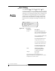
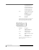
Figure 4-83 Element Response Screen
Parameters Description
Type Indicates the element type
(DRIVE, IE, STOR)
Coord Indicates the element
coordinate location
Index Indicates the database element
index
Address Indicates the current SCSI
element address
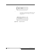
When [more] is selected the Continuation Screen
appears. See Figure 4-84.
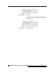
Type: LTO STOR
Coord: S 01 1 A 01
Index : ST 00001
Addr:0X1000[more]