
Operating instructions

Commands Menu 4-47
September 2007
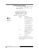
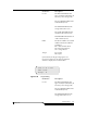
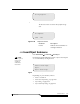
Parameters Description
Coord The first field indicates the
type of cell (I for I/E Station, D
for Drive, S for Storage cell)
The second field indicates the
rack number (01–16)
The third field indicates the
storage cell section (1–5)
The fourth field indicates the
column of the section (A–P)
The fifth field indicates the row
of the column (01–15)
Index The device address associated
with the selected coordinate
parameter:
DT = data transfer device
IE = insert/eject device
ST = storage device
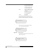
Accept Y to accept
N to reject
If Y is selected, the Target Dialog appears. See
Figure 4-56. Otherwise, the changed parameters
continue to display but no action is taken.
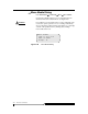
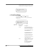
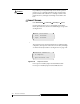
Figure 4-56 Target Dialog
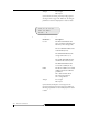
Parameters Description
Coord The first field indicates the
type of cell (I for I/E Station, D
for Drive, S for Storage cell)
The second field indicates the
rack number (01–16)
The third field indicates the
storage cell section (1– 5)
Enter TARGET
Coord: I< 01 1 A 01
Index: 15949
Accept : N