SNC® 6101 Installation and Maintenance Guide ADVANCED DIGITAL INFORMATION CORPORATION www.adic.
Copyright © 2003-2004 ADIC The information contained in this document is subject to change without notice. This document contains proprietary information which is protected by copyright. All rights are reserved. No part of this document may be photocopied, reproduced, or translated to another language without prior written consent of ADIC.
Contents 1 Introduction 1 Intended Audience. . . . . . . . . . . . . . . . . . . . . . . . . . . . . . . . . . . . . . . . . . . . . . . . . . . . . . . . . . . . . . . . . . Associated Documents . . . . . . . . . . . . . . . . . . . . . . . . . . . . . . . . . . . . . . . . . . . . . . . . . . . . . . . . . . . . . . Explanation of Symbols and Notes . . . . . . . . . . . . . . . . . . . . . . . . . . . . . . . . . . . . . . . . . . . . . . . . . . . . . Environmental Notices and Statements . . . . . . .
3 Installation 13 Getting Started . . . . . . . . . . . . . . . . . . . . . . . . . . . . . . . . . . . . . . . . . . . . . . . . . . . . . . . . . . . . . . . . . . . Unpacking and Inspecting . . . . . . . . . . . . . . . . . . . . . . . . . . . . . . . . . . . . . . . . . . . . . . . . . . . . . . . . . . . Pre-Installation. . . . . . . . . . . . . . . . . . . . . . . . . . . . . . . . . . . . . . . . . . . . . . . . . . . . . . . . . . . . . . . . . . . . Installing the SNC 6101 in a Scalar 100 . . . .
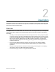
Introduction This manual provides information and instructions that support the installation and operation of the Storage Networking Controller (SNC) 6101. Intended Audience This guide is intended for operators, administrators, and maintenance personnel who interact with the SNC 6101 hardware.
Environmental Notices and Statements Environmental notices and statements that relate to the SNC 6101 include the following topics: Product Recycling This unit contains recyclable materials that must be recycled according to local regulations wherever processing sites are available. Lithium Battery This unit may contain a Lithium battery. WARNING RISK OF FIRE, EXPLOSION, OR BURNS. NEVER SHORT CIRCUIT, CRUSH, HEAT ABOVE 100 ° C, INCINERATE, OR DISASSEMBLE A LITHIUM BATTERY.
• Be very careful when you work with ESD-sensitive parts in cold weather. Low humidity increases static electricity. Getting More Information If you want more information about your product, go to the Scalar 100 website or contact the ADIC Technical Assistance Center (ATAC). Scalar 100 Website For the latest information and accessories for the Scalar 100, visit the product website at www.adic.com/scalar100.
4 Introduction
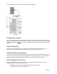
Description This chapter provides a basic overview of the SNC 6101. It describes its main features, illustrates a typical installation in a Scalar 100, identifies all user components available on its front panel, and lists important mechanical and electrical specifications. Overview An integrated SNC 6101 enables Scalar 100 customers to use and manage their library in a storage area network (SAN).
One possible configuration of the of the SNC 6101 is illustrated below. Configuration Support The SNC 6101 provides two Fibre Channel (FC) interfaces. These FC interfaces are configured with small form factor pluggable transceiver (SFP) modules. In addition, the SNC 6101 provides four Ultra320 SCSI interfaces as illustrated in Figure 1 on page 8. These Ultra320 interfaces are capable of both SE and LVD signaling.
• Policy-based event logging and e-mail notification • Device-level diagnostics, reporting, and configuration All of these functions are embedded into a point and click interface designed to simplify management. The AMC receives information from Scalar storage networking libraries using the industry standard SNMP protocol. Because ADIC uses an industry standard protocol, information can be directed from ADIC libraries to framework applications.
Data Mover Module The SNC can move data directly between the storage devices attached to it. This direct movement of data can be from disk to disk, disk to tape, tape to disk or tape to tape. The Data Mover Module frees-up valuable system resources on the server and substantially increases the speed of backup and restore operations. • The Data Mover Module is the engine for Server-Free backup and restore and HSM applications that support the Extended Copy Specification (ANSI T10/99-143r1).
SCSI ports (SCSI 1, SCSI 2, SCSI 3, SCSI 4) Four Ultra-320 Low Voltage Differential/Single-Ended (LVD/ SE) SCSI channels with internal termination are available. These channels have automatic speed and width negotiation capability for wide or narrow bus widths and standard, fast, Ultra, Ultra2, Ultra3 or Ultra320 speeds. These parameters can be viewed from the ADIC Management Console. Service port (null modem) The service port is an RS-232 (DTE) connection with a 9-pin Dshell.
RJ-45 1 RJ-45 2 Each RJ-45 port provides two connection status LEDs. The green LED is ON when the cable is plugged into another active network device. It turns OFF whenever the Ethernet cable is disconnected or the device at the opposite end is powered down or disconnected. The yellow LED flashes to signify port activity. At the time of this printing, Ethernet port #2 was disabled internally. PWR The PWR (Power) LED is ON whenever the SNC 6101 has power applied.
Operating Environment Operating Temperature: 10° C to 40° C (41° F to 113° F) Storage Temperature: –40° C to 70° C (–40° F to 158° F) Humidity: 10%-85% Operating, Non-Condensing, 5%-95% Non-operating, Non-Condensing Note To provide a safety margin and permit adequate cooling, the SNC 6101 is fitted with a 12 VDC tach-output blower. Should temperatures exceed specifications, an environmental alarm violation is sent and logged, permitting environmental causes of failure to be determined.
12 Description
Installation This section provides field procedures for installing and configuring the SNC 6101 for operation with the Scalar 100. At the completion of these procedures, your SNC 6101 will be: • mounted in the Scalar 100 Refer to the section To install the SNC 6101 on page 16. • correctly cabled to the Scalar 100 SCSI devices Refer to the section To connect the SCSI ports on page 17. • running the latest version of firmware Refer to the section To upgrade SNC 6101 Firmware on page 25.
Table 1 Step SNC 6101 Installation Checklist Action Comments and References 1 Unpack and inspect SNC 6101 and accessories. Ensure that the SNC 6101 was received undamaged and with all accessories enclosed. Refer to Unpacking and Inspecting on page 14. 2 Assemble all items used during SNC 6101 installation process. Prior to beginning your installation, you must have acquired all the items identified in Pre-Installation on page 15. 3 Install the SNC 6101 into the Scalar 100 chassis.
2 3 Verify that the these items are included and undamaged: • SNC 6101 module • SCSI cable assembly, HD68-VHDCI • DB9 serial crossover (null modem) cable • CD with Scalar 100 documentation and a CD with SNC 6101 documentation and software At this time, either fill out and mail the registration card or register the SNC 6101 online at www.adic.com.
Installing the SNC 6101 in a Scalar 100 To install the SNC 6101 1 Power down your Scalar 100 and disconnect the AC power cord from the voltage source. 2 At the rear of the Scalar 100, find the bottom, left filler plate (see Figure 4). 3 Remove the filler plate by unscrewing the two thumb screws identified in Figure 4. CAUTION Save this filler plates for future use.
Figure 5 6 SNC 6101 Installation Alignment Push in the two thumb screws identified in Figure 6 and hand tighten only. Figure 6 Scalar 100 with SNC 6101 Installed Cabling the SNC 6101 To connect the SCSI ports 1 Determine your system’s SCSI cable requirements by referring to Figure 7 on page 18, Figure 8 on page 19, Table 2 on page 18, and Table 3 on page 19. Note These figures illustrate the SNC 6101 with the maximum number of drives installed.
2 Route your cables according to the configuration scheme provided in either Figure 7 or Figure 8.
Figure 8 Note Table 3 SCSI Cabling for AIT Drives AIT libraries cannot have tape drives installed in the bottom-most or top-most drive module slots.
Table 4 SNC 6101 SCSI Cable Types From To SCSI 1 Library SCSI 2 SCSI 3 SCSI 4 Tape drive Library Tape drive Tape drive Tape drive SCSI Cable Required Universal SCSI cable with a 68-pin high-density connector at one end and a VHDCI connector at the other. Universal SCSI cable with a 68-pin high-density connector at each end. 3 Insert terminators (high-density 68-pin) in all unused SCSI ports on the drives.
Configuring the SNC 6101 You can configure the SNC 6101 as soon as you have installed it in the Scalar 100 and all appropriate cables are in place. Configuration defines these values for the SNC 6101: • IP address and subnet mask • gateway address • host name Note Configuration requires that you access the SNC 6101 command line interface by connecting the service port (null modem) on the SNC 6101 to an RS-232 DTE terminal or desktop/laptop computer that is running terminal emulation software.
2 On your computer, double-click the HyperTerminal icon (Start> Program> Accessories> Communications> HyperTerminal). 3 In the New Connection dialog box, enter SNC6101 for a name (any name will do) and click OK. 4 In the Connect To dialog box for the Connect using field, select the COM port your computer will be using (COM1, for example) and click OK.
3 After entering the initializeBox command, enable the following SNC 6101 features: a. Data Mover sncFeatureEnable "enable" b. Scalar Firewall Manager sfmFeaturEnable "enable" Note 4 If the value = 1 = 0x1 message is displayed following a feature enable command, the license is installed and the feature already enabled. If a value = -1 is returned, the current license does not support that feature. Use the command licenseShow for a list of features currently licensed for your SNC 6101.
5 Match your actual SCSI connections with the data provided from scsiShow, ensuring that connections are correct and that all devices are present. Note 6 ID “0” is assigned to the library controller; IDs “1” through “5” and “8” through “15” (as needed) are assigned to the tape drives. Drive “1” always begins as the bottom drive. See Figure 7 and Figure 8. If a device fails to appear, verify the installation of all your cable connections and terminators.
SNC > rtcDateSet 2004,1,8,2,13,8,0 Note Use a 24-hour clock and Greenwich Mean Time when setting the RTC. Note A digit from 1-7 must be entered for the [dayofweek] parameter, but it does not matter what you enter, since the command will automatically correct it if it is wrong. 13 Use the dateSetFromRTC command to set the real time clock on the SNC as the source of date display. SNC > dateSetFromRTC value = 0 = 0x0 SNC > 14 Use the tzSet command to set the timezone.
2 Copy the downloaded firmware file to the root directory of drive C and extract it from the self-extracting executable zip file. Note You can use any location, but for simplicity in the FTP process use the root of drive C. 3 Open the command line window on the host. 4 At the command line prompt, use ping to verify your Ethernet connection to the SNC 6101: ping [SN6101 IP address] where [SN6101 IP address] is the assigned IP address for your SNC 6101, for example: ping 192.168.1.
HBA cards contain sensitive electronic components easily damaged by an electrostatic discharge (ESD). To prevent ESD damage while installing your card, maintain frequent contact with any grounded metal surface. Use of a grounding wrist strap is highly recommended. Handle the card carefully at all times, preferably by the edges. Avoid touching electronic components and keep the card in the original packaging until ready for installation.
Verifying SNC 6101 Operation Use the following procedures to verify SNC 6101 connections and configure the FC port, SNMP traps, and e-mail alerts. Use the ADIC Management Console. For more information, refer to the ADIC Management Console User’s Guide. 1 Using the ADIC Management Console, confirm that all attached devices are displayed under each channel. 2 Verify/set configuration values for the FC Port.
Scalar Firewall Manager Scalar Firewall Manager (SFM) is a software feature that collects all host and target information and manages the end-to-end access control in the SAN. It allows the system administrator to control access privileges between individual Host Bus Adapters (HBAs) and target devices connected to the SNC 6101 SCSI and Fibre Channels. The system administrator uses the ADIC Management Console to administrate the SFM.
Host Registration Service The Host Registration Service (HRS) is a small agent installed on the hosts that access the library. HRS simplifies security configuration and allows administrators to monitor host connections to the library. To do this, HRS sends a periodic data pulse through the host’s Fibre Channel HBA to the library. The pulse consists of the host’s WWN, network name, HBA type, and HBA driver level. The SNC 6101 records this information and displays it in the AMC.
Once installed, the service runs automatically and does not require further system administrator interaction. From the ADIC Management Console, you can see the Fibre Channel that the host is connected to and you can tell whether the host is online or offline. For software updates, visit “Service and Support” at www.adic.com. Note You must refresh the SNC 6101 from the ADIC Management Console to see host status changes.
Combining SFM with Channel Zoning In certain instances, it may be an advantage to combine the channel level security of channel zoning with the advanced LUN level security of Scalar Firewall Manager (SFM) to achieve a mix of load balancing and host-specific security. In this situation, channel zoning provides load balancing while SFM delivers resource security and hetergenous host support.
Maintenance This section provides procedures for the removal, replacement, and testing of the SNC 6101. Updating Firmware and Configurations Although the ADIC Management Console (AMC) is the simplest and most efficient tool for updating firmware and saving/loading configurations, the administrator can use the service terminal as an alternate method to perform these operations. For more information on using the AMC to update firmware and configuration, refer to the ADIC Management Console User’s Guide.
Verifying the Terminal Connection When the SNC 6101 is turned on, you can see all characters typed in the terminal. The simplest test is to press Enter. The SNC responds by displaying a command prompt. SNC6101 > For additional commands that are available to control, manage, and service the SNC 6101, refer to the SNC Firmware 4 User’s Guide. When the SNC 6101 is rebooting, several messages are displayed on the service terminal.
1 To prevent a telnet user from locking the command line shell, establish a command line connection to the SNC 6101 and enter: shellLock 1 To unlock the shell enter: shellLock 0 Using Telnet When opening a telnet connection to the SNC 6101, you must ensure that: • A valid user account and password exists • ShellLock is set to 0 • No other administrator is accessing the SNC 6101 through telnet To open a session to the SNC 6101, start telnet and enter open x.x.x.x where x.x.x.
• When possible, keep all ESD-sensitive parts in a grounded metal case. • Be very careful when you work with ESD-sensitive parts in cold weather. Low humidity increases the buildup static electricity. Removing and Replacing the SFP Follow the procedures below to remove and replace the SFP (small form factor pluggable transceiver). CAUTION Shut down the host systems to ensure that all I/O through the SNC 6101 has stopped. Removing the SFP 1 Unplug the Fibre Channel cable.
Replacing the SNC 6101 1 Remove the SNC 6101 from its protective bag. 2 Install it in the Scalar 100 according to the steps available in To install the SNC 6101 on page 16. 3 If it is not imperative for the replacement SNC 6101 to have a WWN identical to the replaced SNC 6101, proceed to the Final Diagnostic Tests on page 41. If the replacement SNC 6101 must have a WWN identical to the replaced SNC 6101, proceed to Changing the WWN.
4 Connect a service terminal to the service port. For the location of this port, refer to Front Panel Interface Ports on page 8 of this User’s Guide. 5 Use the scsiShow command to obtain a detailed listing of all connected SCSI devices as illustrated in To configure the SNC 6101 on page 22. If the output from the scsiShow command is not accurate, ensure that all cable connections and terminators are installed correctly and that all devices are present.
7 After the SNC 6101 reboots, use fcShowNames to verify your changes. Verify that the output in the Node Name column is correct. Changing a WWN for one FC port Use the following procedure when you replace another vendor’s appliance with an SNC 6101 and it is critical that one of the replacement SNC FC ports retain the same WWN as the FC port of the replaced appliance.
Clearing Changes to the WWN for all FC ports Use this procedure when you are removing an SNC 6101 that had its WWNs changed to match a preexisting unit. 1 Read the section Changing the WWN on page 37. 2 Follow the instructions in Before Changing the WWN on a Replacement SNC 6101 on page 37. CAUTION 3 The WWN override functions are available only through the service port. These commands cannot be executed if attempted in a telnet session. Enter the wwnGlobalClear command.
4 Type “yes” and press ENTER. You are prompted for the password. 5 Key in the password OverrideWWN and press ENTER. This causes the SNC to reboot. 6 After the SNC has rebooted, use the fcShowNames command to verify your changes. The output in the Node Name column of the of the fcShowNames command should no longer match the output previously saved before using wwnGlobalClear.
Ethernet Test Note 1 Ethernet port “2” is disabled internally. Omit testing of this port. Obtain the Ethernet network parameters for the SNC 6101. For more information, refer to To configure the SNC 6101 on page 22. 2 Attach the Ethernet loop back plug to the Ethernet port. 3 From the service terminal, enter the elTest command. 4 If the test passes, go to Step 5. 5 Remove the Ethernet loop back plug.
Post-Repair Checklist To ensure a successful SNC 6101 installation, it is important that the items in this checklist be verified after you have completed the replacement process. Table 5 Step Post Replacement Checklist Actions Comments and References 1 Install the replacement SNC 6101 in the Scalar 100. Refer to Replacing the SNC 6101 on page 37. 2 Ensure that the FC hosts are turned off. If not, disconnect the FC cables now.
Table 5 Step 44 Post Replacement Checklist Actions Comments and References 11 At the service terminal, enter the fcShow command to view the status of each FC interface that is installed and connected. In the output of the fcShow command, look for the Firmware State column. 12 From the service terminal, enter the fcShowDevs command to show the SCSI target devices that are connected as seen by the Fibre Channel interface. Check to see that all SCSI target devices are seen by each FC interface.
Index A access security . . . . . . . . . . . . . . . . . . . . . . . . . . .7 accessories, SNC 6101 . . . . . . . . . . . . . . . . . . .15 address mapping . . . . . . . . . . . . . . . . . . . . . . 2, 6 ADIC Management Console . . . . . . . . . . . . . . . . . . 6 ADIC Management Console . . . . . . . . . . . . . . . .28 AIT drive . . . . . . . . . . . . . . . . . . . . . . . . . . . . . . .19 ATAC contacting . . . . . . . . . . . . . . . . . . . . . . . . . . . 3 training . . . . . . . . . . . . . . . .
environment, operating humidity . . . . . . . . . . . . . . . . . . . . . . . . . . . . 11 environmental notices . . . . . . . . . . . . . . . . . . . . . .2 ERR LED . . . . . . . . . . . . . . . . . . . . . . . . . . . . . .10 ESD caution . . . . . . . . . . . . . . . . . . . . . . . . . . . . . 27 handling parts . . . . . . . . . . . . . . . . . . . . . . . 35 ethAddrGet . . . . . . . . . . . . . . . . . . . . . . . . . . . . .24 ethAddrSet . . . . . . . . . . . . . . . . . . . . . . . . . . . . .
removing SFP . . . . . . . . . . . . . . . . . . . . . . . . . . . . . . . 36 SNC 6101 . . . . . . . . . . . . . . . . . . . . . . . . . . 36 replacement procedures . . . . . . . . . . . . . . . . . . .35 replacing SFP . . . . . . . . . . . . . . . . . . . . . . . . . . . . . . . 36 SNC 6101 . . . . . . . . . . . . . . . . . . . . . . . . . . 36 restrictions, usage . . . . . . . . . . . . . . . . . . . . . . . .2 ridTag . . . . . . . . . . . . . . . . . . . . . . . . . . . . . . . . .42 RS-232 . . . . . . .
48 Index