® 8000 Removable Hard Disk Storage System User Guide PN 6-67387-03 Rev A
FCC This device complies with part 15 of the FCC Rules. Operation is subject to the following two conditions: (1) This device may not cause harmful interference, and (2) this device must accept any interference received, including interference that may cause undesired operation. Commercial use statement: NOTE: This equipment has been tested and found to comply with the limits for a Class A digital device, pursuant to part 15 of the FCC Rules.
Table of Contents Introduction ...........................................................................................................................................6 1. Scope ............................................................................................................................................................................... 6 2. Contact Quantum ......................................................................................................................................
5.5 Cartridge Ejection ................................................................................................................................................... 24 5.6 Introduction to the RDX 8000 ............................................................................................................................... 26 5.6.1 RDX 8000 Flow Chart ............................................................................................................................. 26 5.
7.1.3 Remote notification handling related errors ......................................................................................... 73 7.1.4 System related errors ............................................................................................................................ 74 C. Appendix .......................................................................................................................................... 75 1. Product specification .................................
B A. Introduction 1. Scope This document provides information about installing, operating, troubleshooting, and servicing an RDX 8000 product. This document is intended for system administrators and users who need information on the RDX 8000 product. 2. Contact Quantum www.quantum.com/serviceandsupport .
Product Description 1. Introduction to the RDX 8000 1.1 Overview and applications The RDX 8000 is a multi-cartridge data storage device designed to support up to 8 RDX cartridges. It may be utilized as a table top unit or rack mounted in a 2U high space with the included rack mounting ears. The RDX 8000 connects to the user’s computer network via one or two 1 GB/sec network port using iSCSI protocol.
1.4 Operation modes The RDX 8000 is capable of being configured during installation by the user to present up to eight RDX cartridges to the host system (via the iSCSI Initiator) as one of three different configurations of RDX based storage devices. The appropriate operating mode can be selected to support the intended application and data management/backup application in use. Please see the online RDX 8000 software-compatibility matrix http://www.quantum.com/ServiceandSupport/ CompatibilityGuides/Index.
2. Front panel The front panel of the RDX 8000 is constructed of durable plastic and is designed to provide both visual appeal and protection from entry of dust/dirt. The eight spring-loaded cartridge bay doors prevent entry of dust when no cartridge is inserted, protect the unit from ESD, and control the cooling airflow through the device. The bezel surface may be cleaned with a water dampened lint free cloth. 2.
2.2 LED Behavior 2.2.1 Power button LED State Blinking green Status No power Unit starting Description No AC Power is present at the RDX 8000 rear connector. Unit is in the process of becoming ready for operation. Steady green Power on Unit is ready for operation. Blinking amber Unit shutting down Standby Unit is in the process of shutting down. Off Steady amber Unit is in standby, AC power is present. 2.2.
3. Rear panel The rear panel of the RDX 8000 provides access to the power connector, Ethernet ports, power supply and cooling fan. 3.
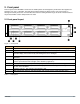
3.2 Ethernet port LED behavior Figure 3 — Ethernet port Number Description 1 Link/Activity LED: Blinking – indicates a link is established. Off – indicates no link is established 2 Speed LED: Amber on – indicates a Gigabit connection (1000 Mbps). Green on – indicates a 100-Mbps connection. Off – indicates a 10-Mbps connection.
4. Product installation 4.1 General installation considerations This section provides instructions for installing the RDX 8000. 4.1.1 Selecting a location Select a location that meets the following criteria: Criteria Definition Mounting orientation Rack requirements Horizontal only-either sitting on a table top or mounted in a 19” equipment rack via the included rack mount ears. The RDX 8000 weighs 15.7 lbs (7.
4.1.2 Installation precautions Select a location that meets the following criteria: CAUTION NOTICE Static sensitive Risk of damage to devices • A discharge of static electricity damages static-sensitive devices or micro circuitry. • Proper packaging and grounding techniques are necessary precautions to prevent damage. • • • Do not expose the unit to moisture. Use the unit on a firm level surface free from vibration. Do not place anything on top of the unit. 4.1.
Identifying the product components Confirm that you received the following accessories in the over pack box (some items optional depending upon the user configuration): • Power cord (region dependent) • Printed Quick Start Guide • RDX cartridges Confirm that you received the following in the RDX 8000 box: • RDX 8000 unit • Rack mounting ears with included mounting hardware • Torx driver for installing rack mounting ears Required additional equipment for a successful installation: • Ethernet cable • RDX cart
4.2 Installing in a rack NOTICE First read Section “14” on page 14. If the unit will not be rack-mounted, skip to “4.3 Installing cables and connections” on page 17. Required tools: • #3 Phillips screwdriver Rack mounting the RDX 8000: 1. Determine the location in the rack for the unit to be installed. 2. Use a pencil to mark the location on each vertical rail in the rack. 3. Install the rack ears of the unit using T10 Torx screwdriver to tighten the Torx screws included in the rack mount kit.
4.3 Installing cables and connections DANGER WARNING High voltage Risk of electric shock • Do not remove cover. No user-serviceable parts are inside. • Refer servicing to qualified service personnel. Usage of unapproved power cords Risk of personal injury Risk of damage to devices Before connecting a power cord to the unit: • Ensure that the power cord meets individual country specific safety requirements. • Use a sufficient conductor amp capacity to avoid overheating the unit.
4.5 Powering up and powering down the unit The RDX 8000 power button indicator will be solid amber when AC power is present at the unit indicating the unit is in Standby mode. Press and release the power button on the front panel to power up the RDX 8000. During the power up process the power button indicator will change from solid amber to flashing green indicating the unit is in the process of becoming ready. The RDX 8000 unit will take approximately 3.5 minutes to complete the power up boot sequence.
5. Product configuration 5.1 Product configuration process Once the RDX 8000 unit has been powered up the unit may be configured to the user’s desired network settings and operational mode. The unit may be configured via the built in RDX 8000 (Remote Management Interface). The RDX 8000 is accessed over the customer’s local IP network using an internet browser application. The RDX 8000 is compatible with the following internet browser applications: • Mozilla Firefox • Internet Explorer • Google Chrome 5.
5.3.1 OCP Display Content Once the RDX 8000 unit completes the power up boot sequence the OCP will become active. The OCP will display the system information screen which identifies the unit’s iSCSI QN name, current IP address / status of Ethernet port 1, as well as the unit current firmware revision level. The normal display mode rotates through nine screens. The System Information screen is followed by eight individual screens indicating slot status.
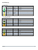
5.3.2 OCP Icons The RDX 8000 makes use of graphic icons to indicate some conditions to the user. These icons are used both on the local OCP display and in the Active System Graphic in the RDX 8000. The RDX 8000 icons in use are shown in the table below.
5.4 iSCSI Connection The RDX 8000 uses the iSCSI protocol to communicate data with the host system. Depending on the operating mode, the RDX 8000 will present itself as one or more iSCSI identities: JBOD mode: The RDX 8000 will present each of the eight slots as a separate iSCSI target. The target iqn’s will have the format of unit iqn with a ”-x” appended at the end, where “x” is the slot number Tape Library Mode: The RDX 8000 will present itself as a single iSCSI target.
9. If the System Mode is Tape Library: In Device Manager. The RDX 8000 will be identified as a Media Changer and a tape drive. 10. If the System Mode is JBOD: In Disk Management 8 Removable Media drives will be identified. Depending on the host operating system, 8 drives may be visible in Windows Explorer.
Linux CentOS: Use the following commands to install the iSCSI Initiator and Connect and Disconnect the RDX 8000 as an iSCSI Target in Linux operating systems: To Connect: 1. Install Open-iSCSI initiator by entering the following command: # yum install iscsi-initiator-utils For Ubuntu and Debian operating systems, enter the following command: $ sudo apt-get install open-iscsi 2.
To install the service: 1. Download the RDX 8000 Utility file to a known location on your host. 2. Extract the files from the .zip file using Right-click - Extract from the operating system, or use another unzip application. The folder contains applications for both 32bit and 64bit operating systems. 3. Double-click the application that is appropriate for your operating system. The installer begins the service and utility installation process.
5.6 Introduction to the RDX 8000 The RDX 8000 unit uses the Web based RDX 8000 to allow the user to configure and monitor the unit. The RDX 8000 IP address may be viewed in the OCP and is displayed between the cartridge monitoring pages for slot 8 and slot 1 (#1 out of 9 screens in continuous rotation). Once the RDX 8000 IP address is known, browse to the unit with your Web browser application by entering the RDX 8000 IP address in your browser address bar. You may enter “XXX.XXX.XXX.
5.7 Login Procedures Access the RDX 8000 remote management interface via a Web browser. Using the IP address visible on the unit's front panel OCP, enter the IP address into) QUr browser address bar and navigate to the RDX 8000 Login page. 5.7.
Figure 11 — RDX 8000 Login Detail Number Description 1 System Name: Displays the name currently assigned to the RDX 8000 unit. The factory default setting is “RDX 8000”. This field may be changed on the “CONFIGURE/Device” tab. This field may only consist of alphanumeric characters. 2 Date & Time: The current system date and time is displayed in MM/DD/YY and 12 Hr. time format. This field may be changed on the “CONFIGURE/Date & Time” tab. These fields may only consist of alphanumeric characters.
5.7.2 SSL Encryption Page Selecting SSL encryption will cause the following screen to be displayed. Figure 12 — SSL Encryption Warning Select “Continue to this Web site.” 5.7.3 RDX 8000 features: • The RDX 8000 grants access or ability to perform operations based upon user rights. • The RDX 8000 grants the Administrator and Service levels full access to device set up, diagnostics, and logging. • The RDX 8000 grants the User level only the ability to monitor device and cartridge status.
5.8 RDX 8000 Pages Upon a successful login into the RDX 8000 all users will be directed to the RDX 8000 “MONITOR/Cartridge Status” tab. An overview of the main graphic elements is displayed below. The main navigation is performed via selection (via mouse click) of the Main Topic Bar (element 1 in the RDX 8000 page chart) and then selection of the associated Sub Topics (element 2).
Numb Description 1 Logged in user / Login user level: This field is visible on all pages. It shows the current user account name and user credential level 2 3 4 5 6 7 RDX 8000 Main topic bar: This field is visible on all pages. The four main RDX 8000 RMI menus are accessed from this set of choices by selecting with a point and click. Operators with User level credentials will not have access to the “MANAGE”, “CONFIGURE” and “DIAGNOSTIC” menus. Sub topic bar: This field is visible on all pages.
5.8.2 RDX 8000 System Information Block The System Information Block provides an overview of global system information. The fields are summarized below. Figure 14 — RDX 8000 System Information Status: This graphic indicates the global system status by color; green indicates good status, yellow indicates warning status, red indicates critical error status.
5.9 Monitoring cartridge and device status – The MONITOR tab The RDX 8000 unit user home page is the “MONITOR” tab for all account logins. Following is a brief description of each function. 5.9.1 Cartridge Status page This section depicts the Monitor Cartridge Status page and describes each field on the page. Figure 15 — RDX 8000 Monitor Cartridge Status Slot #: This field shows the row heading indicating the slot number. Status: OK -- indicates normal operation of the cartridge.
5.9.2 Cartridge Identity page This section depicts the Monitor Cartridge Identity page and describes each field on the page. Table 8 — RDX 8000 Monitor Cartridge Identify Slot #: This field shows the row heading indicating the slot number. SN#: This field displays the physical RDX cartridge serial number. Label: This field displays the cartridge label. Note that this label field will always display the default cartridge label when the RDX 8000 system is operated in JBOD mode.
5.9.3 Device Status page This section depicts the Monitor Device Status page and describes each field on the page. Figure 16 — RDX 8000 Monitor Device Status Status: This field displays the overall system status. Name: This field displays the System Name. IP Address: This field displays the IP address for the device. This address is used to provide access both to the RDX 8000 connection and the iSCSI connection.
Fan Speed: This field displays at which of 4 speeds the fan is currently running. Fan Status: This field displays the system fan status -- Fan OK or Fan Error. The Fan Status will be set to Fan Error if: the fan is not running, not running at the proper speed, or if an over temperature condition is sensed. Power Supply Status: This field displays the power supply status -- Power Good or Power Error.
5.9.4 Network Status Page This section depicts the Monitor Network Status page and describes each field on the page. Figure 17 — RDX 8000 Monitor Network Status IP Address: This field displays the primary IP address of the RDX 8000. Bonding Mode: This field displays the active bonding mode of the RDX 8000. MAC Address: This field displays the main hardware Media Access Control address for the unit. The MAC address is a worldwide unique address assigned to the unit.
5.9.5 Device Identity Page This section depicts the Monitor Device Identity page and describes each field on the page. Figure 18 — RDX 8000 Monitor Device Identity Vendor ID: This field shows the manufacturer of the RDX 8000 device. Product ID: This field shows the product name. Serial Number: This field shows the master serial number of the unit. Firmware Version: This field shows the current firmware revision level and firmware checksum.
5.10 Managing the unit – The MANAGE tab Access to the Manage functions is granted to Administrator and Service level account logins. Following are the levels of the “MANAGE” tab. 5.10.1 Managing the library The “MANAGE/Library” function is available when the operation mode of the RDX 8000 unit is set to “Tape Library”. In “Tape Library” mode, this feature allows the user to “manually move” tape formatted RDX cartridges from any storage slot to the virtual tape drive(s).
5.10.2 Ejecting cartridges Depending on the RDX 8000 System Mode, and current activity, cartridges may be ejected on the MANAGE/Eject Cartridge screen. The cartridge is ejected by selecting the appropriate slot from the drop down menu and clicking the Eject button. In Tape Library mode, the software application may lock the cartridges from local eject and require that they are ejected through the software application.
5.10.3 Initializing cartridges The RDX 8000 uses a specially format on the RDX cartridges to support emulation of tape. In order to apply this special format the user performs a “pre-format” operation via the Initialize Cartridge function. This cartridge formatting operation is only necessary to perform once and it is suggested the user prepare all cartridges which will be used in the media pool at one time. Pre-formatting is only required if the system will be used in Tape Library mode.
An attempt to format a cartridge which has the write-protect switch set will result in “Cartridge in Slot X Activated Failed”. NOTICE Initializing the RDX cartridge into tape mode or from tape format back to disk format destroys any previously written user data on the cartridge. The RDX cartridge will contain no user data and will be blank.
The Operating Mode selected will apply to all eight slots of the RDX 8000 unit.
Figure 23 — RDX 8000 Configure Device - Tape Library Mode To change the RDX 8000 operating mode, select the desired operation mode from the System Mode box. Click the “Submit” button to apply the changes. A confirmation dialog will appear as follows: NOTICE A change in the operating mode of the RDX 8000 may cause the device to become unavailable for data access for your particular environment.
Listed below is a description of the fields and selections on this page. JBOD mode JBOD mode allows the RDX 8000 to appear to the host operating system as 8 individual storage drives -- each with their own drive letter. Tape Library mode The RDX 8000 tape library mode allows data to be recorded to sequentially to RDX cartridges like traditional backup tape devices.
5.11.2 Setting the RDX 8000 Wake up/Sleep mode - CONFIGURE/Device/Power save Timer The RDX 8000 has the ability to schedule auto power on and auto power off events. The user may set both a daily power on time and a daily power off time and choose to enable each one individually. The power off time will shut down the unit at the configured and enabled shutdown time regardless of the status of any data (read/write) activity. Time is entered in HH:MM:SS:AM/PM format.
5.11.3 Cartridge - Labeling tape format cartridges In Tape Library mode the user may label tape formatted cartridges. Custom RDX cartridge labeling may be created under the “CONFIGURE/Cartridge” menu. To alter the cartridge label, click Edit for the desired cartridge. There will be a pop up dialogue where the user may enter a custom label up to 25 characters long. This custom label will both be displayed in the RDX 8000 and shown as the volume label in the tape backup application.
5.11.4 Network settings The "CONFIGURE/Network" tab allows the user to configure the parameters for the network interface. Figure 26-RDX 8000 Configure Ethernet MTU Size: The Maximum Transmission Unit (MTU) Size controls the maximum data packet size orframesizeover the network. The choices are1500 (standard frame) and 9000 – 1500 (jumbo frame) is the default size. Stack: The Stack selects the version of the Internet protocol the RDX 8000 will use when communicating on the network.
IP Address: Manually assigned IP address that the RDX 8000 will use for network communication. Netmask: Netmask used for network communication. Gateway: IP Address of gateway in network. DNS1: A DNS server allows the RDX 8000 to communicate with other network clients via their host name. Enter the IP Address of preferred DNS server. DNS2: IP Address of secondary DNS server. To save the changes made on this page click the “Submit” button.
5.11.5 iSCSI Settings iSCSI settings are accessed on the “CONFIGURE/iSCSI” tab: Figure 28 — RDX 8000 Configure iSCSI Target IQN: The user can assign a unique IQN name to the RDX 8000 unit, overwriting the default IQN value. An IQN may be up to 255 characters long. To apply a new IQN name to the device enters the desired IQN the IQN field. To save any changes on this page, click the “Submit” button.
Figure 29 — RDX 8000 Configure iSNS Server Internet Storage Name Service (iSNS) This field allows for the automated discovery, management, and configuration of iSCSI devices from a central point. If this option is enabled the RDX 8000 will register its resources with a central iSNS-server. To enable iSNS on the RDX 8000, click the check box “Enable iSNS” and enter the IP address for the iSNS-Server in the “iSNS Server” field. To save changes to this page click the “Submit” button.
Figure 30 — RDX 8000 Configure CHAP CHAP is an authentication scheme used by servers to validate the identity of clients and vice versa. When CHAP is enabled, the initiator must send the correct “Username” and “Target Secret” to gain access to the RDX 8000. The “Initiator Secret” field is provided to allow iSCSI mutual CHAP. If mutual CHAP is selected on the Initiator, the RDX 8000 will authenticate itself with the initiator using the supplied Initiator Secret.
5.11.6 User settings The Users tab allows the user to edit existing user accounts and to create new accounts. Administrator level users may edit Administrator and User level accounts. Service level users may edit all account levels. Figure 31 — RDX 8000 Configure Users New user accounts may be created by selecting the “Add User” button. Existing user accounts may be edited by clicking “Edit” in the Action column for the appropriate user account.
Administrator Level: Administrator level grants access to all functions within the unit including “MONITOR”, “CONFIGURE”, “MANAGE” and “DIAGNOSTICS”. Service Level: Service level grants access to all the same functions as Administrator and allows clearing the System Logs. Figure 32 — Add/Edit user account 5.11.7 Date and time settings The Date and Time Settings page allows the user to set the system date and time.
Figure 33 — RDX 8000 Configure Time Zone Date/Time The date may be set by clicking in the date field and entering the date in the appropriate format and click Done. The time may be set by clicking in the time field and entering the time. Clicking the “Now” button will synchronize the RDX 8000 system time with the time of the computer accessing the RDX 8000. Save the changes to the date and time by clicking the “Submit” button.
Figure 34 — RDX 8000 Configure Date/Time Date/Time Format The Date/Time Format tab allows the user to set the display format of the date and time zone independently.
Figure 35-RDX 8000 Configure Date/Time Format RDX 8000 57
NTP The NTP tab allows the administrator to set a path to a Network Time Server (if an NTP server is configured on their particular network). The RDX 8000 will synchronize with the NTP time server every eight hours. To use the NTP time synchronization, select Enable and enter the name or IP address of the desired time server. Click the Submit button for the settings to take effect. The first time synchronization will take place when “Submit” is clicked.
5.11.8 Notification settings E-mail Notification allows the user to configure the RDX 8000 to send e-mail to a selected account upon an identified level of system event. The Notification tab has the following fields: Enable E-mail notification: This check box will enable The E-mail Notification action, and will allow the user to configure the e-mail parameters.
Notification Filter: Select from four classes of notification as follows: Critical Events: Notified whenever severe errors requiring operator intervention to resolve occur, or when a hardware failure is detected. Critical, Warning, Configuration Events: Notified whenever any Critical or Warning or Configuration events occur which indicate changes in unit configuration, operating mode, addition of users, etc.
5.11.9 Save/Restore configuration Save Configuration: This tab allows a user to save the current user programmed configuration values/settings. This allows the backup of settings and also supports unit replacement/service. The Configuration file may be stored to a location on the RDX 8000 host computer via selecting the Save Configuration button and downloading the file.
Figure 39 — RDX 8000 Restore Configuration Reset Configuration: This function restores all factory default settings, including resetting default passwords, IP addressing, and operating modes. Depending on network settings resetting defaults may cause loss of communication with the unit or require you to adjust network settings to regain access to the unit.
5.12 Performing Diagnostic operations - The DIAGNOSTICS tab 5.12.1 Device Logs The RDX 8000 unit supports a built in event logging feature designed to facilitate monitoring and trouble shooting of the device. The logs are available for viewing under the “DIAGNOSTICS/Device Logs” tab. Within the “Device Logs” tab the user has the option of filtering the log view as follows; Errors: Errors are critical events that indicate either a failure in hardware or a major software issue.
5.12.2 Performing diagnostics The RDX 8000 unit supports a number of interactive diagnostic tests designed to check specific areas of operation of the device. The tests are all designed to be executed with a local observer so the unit’s behavior can be monitored for expected behavior. OCP diagnostics There is a simple display diagnostic which can be invoked from the front panel which allows quick verification of the front panel indicators.
RDX 8000 Diagnostics The RDX 8000 unit supports a number of interactive diagnostic tests designed to check specific areas of operation of the device. The tests are all designed to be executed locally so the unit’s behavior can be observed. The tests are as follows: Slot UI Test: It tests each slot for eject button indication and sensing- requires a local operator to interact with the unit.
Slot UI Test Figure 41 — Slot UI Test To execute the “Slot UI Test” select the “Start Test” button. It which will request the operator to push each individual slot eject button and observe the LED behavior. The LED will blink three times green then three times amber. Note that when the RDX 8000 is in the slot UI test mode any inserted cartridge will not be ejected by the associated button push during the test.
Figure 43 — Display Test Results Once all six display conditions have been verified confirm completion of a successful test by selecting “Test Passed” button which will create a “Display Test passed” status. Fan Test Figure 44 — Fan Test To execute the Fan Test select the “Start Test” button. The fan will cycle through four operation speeds while monitoring the fan RPM for the correct reference value.
To execute the Cartridge Access Test select the “Start Test” button, the RDX 8000 unit will then bulk eject all currently inserted cartridges and ask the user to remove them from the unit. Figure 46 — Cartridge Access Test The operator will then be asked to insert a cartridge in each of the eight slots in sequence. The RDX 8000 unit will then perform the slot access test and eject the cartridge and provide a pass/fall status.
5.12.3 Upgrade Firmware The user can upgrade the unit operating firmware via the “DIAGNOSTICS/Upgrade Firmware” tab. Released firmware images are available via the RDX 8000 support team. RDX 8000 firmware images have an “.fbi” file extension and are approximately ~22MB in size. Click the “Browse” button to set a path to the RDX 8000 firmware file located on the computer system connect via RDX 8000, then select the “Upgrade” button.
5.12.4 Reboot The RDX 8000 may be rebooted remotely via the “DIAGNOSTICS/Reboot” tab selecting the “Reboot” tab and clicking the “Reboot” button. Rebooting the unit takes approximately 3.5 minutes and will require the user to log in to the RDX 8000 again after the reboot process is complete.
6. RDX cartridges This section describes the use of the RDX cartridge in the RDX 8000. The RDX cartridge utilizes a removable 2.5” mobileHDD to offer the reliability and performance of disk technology along with the manageability of removable media. For physical and functional specifications, please see section “1. Product specification” on page 75. Figure 50 — Cartridge overview RDX cartridges contain HDDs with SATA I or SATA II interfaces capable of transferring data at either1.5 GB/s or 3.0 GB/s. 6.
6.2 Inserting cartridges 1. Find an empty RDX cartridge slot (8 places) in the unit to be inserted. 2. Push the RDX cartridge gently into the cartridge slot until it seats itself against the back of the unit. 3. Verify that the cartridge is properly inserted. When the cartridge indicator LED is steady green the cartridge is ready. Figure 52 — Inserting cartridges 6.
Front Panel Cartridge Eject button When allowed by the application in Tape Library mode, or when not Ejection Protected in JBOD mode, cartridges may be ejected via the Cartridge Eject button. Cartridges are ejected by pressing the Cartridge Eject button for the appropriate slot for approximately 2 seconds. If ejection is allowed, the eject button will flash green and the cartridge will eject shortly. If ejection is not allowed, the eject button will flash amber and cartridge will not be ejected.
7. Troubleshooting 7.1 Error Messages 7.1.1 Network related errors Text shown to user interfaces Description Possible solution Set network configuration failed Error while writing “network configuration” values to database or Error while executing “network fi is no ti link ” detected i t There for the network port that is being configured. One possible cause for this error is that no network bl iwasl no answer di There from a Check if the network settings are correct.
7.1.4 System related errors Text shown to user interfaces Description Possible solution Fan speed out of range Fan speed out of range, speed too slow. Fan is not fully installed. Fan is obstructed. Voltage out of range At least one voltage is out of Defective power supply. Temperature on local sensor under low limit Temperature on CPU board exceeds lower alarm level. Fan and/or system airflow is obstructed.
C. Appendix 1. Product specification 1.1 Physical specification Mechanical dimension and unit height 1. Unit Height: 2U with clearance for units above and below 2. Unit Depth: Less than 12” (excluding connectors) 3. Unit Width: Fits standard 19” computer racks 4. Standalone Unit Weight, (without a disk): 6.0 kg 5. Packaged Unit Weight, (with accessory kit, without disks): 8.0 kg 6. Single Disk Weight (without plastic box): 0.170 kg 0.240 kg 7. Single Packaged Disk Weight (with plastic box): 1.
1.3 Regulatory Requirements Product Safety: • CB Report and Certification with all national deviations, according: • IEC 60950-1:2005 • EN 60950-1:2006 + A11:2009 • UL 60950-1 Issued 2007/03/27 Ed. 2 • CSA-C22.2 No. 60950 Issued 2007/03/01 Ed. 2 Emission: Limit: Class A • IEC CISPR 22:2008-09 Ed. 6.0 • EN 55022:2006 + A1:2007 Limit: Class A Limit: Class A (Test acc. to CISPR 22) • FCC: 47CFR Part 15B:2008-07 • ICES-003, Issue 4 2004-03 Limit: Class A (Test acc.
2. CRU replacement 2.1 Power supply The power supply is a CRU (Customer Replaceable Unit). The power supply is located on the rear side of the unit and is fixed with two thumb screws. The power supply is capable to power up to 8 cartridges simultaneously while supporting other unit electronics (controller, LED`s, OCP, motors). For technical specification, see section “1. Product specification” on page 75. 2.1.1 Removing a power supply 1. Power down the unit by pressing the power button on the front panel.
2.2 Cooling fan The cooling fan is a CRU (Customer Replaceable Unit)). The fan is located on the rear side of the unit and is fixed with 2 thumb screws. The fan is speed controlled. The speed varies in 4 steps (low, medium, high and max) and is controlled by a micro controller and thermal sensors. For technical specification, see section ”1. Product specification” on page 75. 2.2.1 Removing a cooling fan 1. Power down the unit by pressing the power button on the front panel. 2.
3. RDX 8000 Jumbo Frames configuration Optimum RDX 8000 performance can be achieved in all operating Modes (JBOD and Tape Library) through a Jumbo Frames configuration.
5. Select Jumbo Packet (or Jumbo Frame) in the Property List. Set the value to 9000. Click OK. 6. If your Property List does not include Jumbo Packets/Frames (as in the example below), you will need to update the driver for the network card. Check the network card manufacturer website for the latest drivers. 7. On the Connection Properties Box for the network port, select the Internet Protocol 4 (IPv4) and click Properties. 8. Click “Use the following IP Address” and enter an IP address for the port.
11. Go to Configure – Network. 12. Click on MTU box and select 9000 13. Click on Manual in the Set IP address. nd 14. Set IP appropriate for address configured on 2 network port. For example: if 192.168.64.10, then set ip to 192.168.64.11, mask as 255.255.255.0 and gateway as 192.168.64.
15. Click Submit. After 30-60 seconds new IP address will show in OCP. 16. Disconnect RDX 8000 from primary network. nd 17. Connect RDX 8000 to 2 network port using cross-over cable if direct connect. Or use gigabit jumbo frames nd capable network switch, and connect both 2 network port and RDX 8000 to it. 18. Using the browser on the server, go to the ip address configured on the RDX 8000. The log-in page should appear.
D. Glossary Term Description CRU Customer Replaceable Unit is easily replaceable module designed to enable customer serviceability of the RDX 8000 unit. CRU’s can be exchanged by the end use customer without tools to support field renew/repair of either the cooling fan or power supply system. DHCP The Dynamic Host Configuration Protocol is an automatic configuration protocol used on IP net- works.
Term Description SCSI Small Computer System Interface is a set of standards for physically connecting and transferring data between computers and peripheral devices. The RDX 8000 uses the SCSI protocol transmitted via iSCSI packets over the user’s computer network. SMI-S SMI-S, or the Storage Management Initiative Specification, is a storage standard developed and maintained by the Storage Networking Industry Association (SNIA). It has also been ratified as an ISO standard.