Quantum PX720 Unpacking and Installation Instructions Introduction 3 Selecting an Installation Location 4 Floor Space..................................................................................................................4 Floor Clearance ..........................................................................................................5 Floor Strength and Inclination.................................................................................5 Power and Grounding .................
Quantum PX720 Unpacking and Installation Instructions Document 6444602-04 A01 March 2005 2 6207947-05fN 19 c
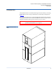
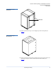
Quantum PX720 Unpacking and Installation Instructions Document 6444602-04 A01 March 2005 Introduction 0 The Quantum PX720 is an automated storage and retrieval library consisting of up to 20 tape drives and up to 642 SDLT or 726 LTO tape cartridges bins (figure 1). This document explains how to unpack the Quantum PX720. Once the library is unpacked and moved to the desired installation location, set up the library using the instructions in the Quantum PX720 Series User’s Guide.
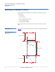
Quantum PX720 Unpacking and Installation Instructions Document 6444602-04 A01 March 2005 Selecting an Installation Location 0 When choosing an installation site for the PX720, consider the following requirements: • Floor space • Floor clearance • Floor strength and inclination • Power and grounding • Environmental conditions These requirements are also described in the Quantum PX720 Series User’s Guide. Floor Space 0 Figure 2 shows the minimum floor space required by the Quantum PX720.
Quantum PX720 Unpacking and Installation Instructions Document 6444602-04 A01 March 2005 Floor Clearance 0 Floor Strength and Inclination 0 The library has a floor clearance of 0.75 inch (19 mm). Place the library on a level, uncarpeted floor free of defects. The floor at the installation site must be rated at 250 lb/ft2 (1221 kg/m2). This is sufficient to support a fully loaded PX720 library. The floor must be level to within 0.25 inch (6.4 mm) over a 6-foot-by-6-foot (1.83-meter-by-1.83-meter) area.
Quantum PX720 Unpacking and Installation Instructions Document 6444602-04 A01 March 2005 Environmental Conditions The installation site must have the following environmental conditions: 0 • Humidity: 20%-80% non-condensing • Temperature: 15°C-32°C (59°F-90°F) • Altitude: sea level to 3048 meters (10,000 feet) These environmental conditions apply when the library is in operation.
Quantum PX720 Unpacking and Installation Instructions Document 6444602-04 A01 March 2005 • Avoid contact with power supplies, EMI filters, and AC electrical components while the library is connected to a power outlet. • Use an antistatic wrist strap. • Keep static-sensitive parts in their original shipping containers until ready for installation. • Do not place static-sensitive parts on a metal surface. Place them inside their protective shipping bag or on an antistatic mat.
Quantum PX720 Unpacking and Installation Instructions Document 6444602-04 A01 March 2005 Unboxing the Library 0 To unbox the library: 1 Check the packing list and verify that all components have been received. Note: If any part is missing or damaged (look for scuffs on the antistatic bag), contact your authorized reseller. 2 Choose the unloading side. The PX720 may be unloaded from only the right side of the pallet. 3 Verify the minimum floor space requirements (see figure 5).
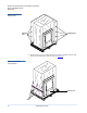
Quantum PX720 Unpacking and Installation Instructions Document 6444602-04 A01 March 2005 Figure 6 Removing the Steel Bands Steel bands 5 Lift the cardboard box top cover straight up and off of the pallet (see figure 7). Figure 7 Removing the Box Top Cover 6 Remove the eight cardboard box retaining clips to their open position and unwrap the two pieces of the cardboard box from the library (see figure 8).
Quantum PX720 Unpacking and Installation Instructions Document 6444602-04 A01 March 2005 Figure 8 Removing the Cardboard Box Retaining clips Retaining clips 7 Remove the 3-3/8 in. hex head bolts, lock washers, and flat washers from the front rail of the pallet and set aside (see figure 9).
Quantum PX720 Unpacking and Installation Instructions Document 6444602-04 A01 March 2005 8 Remove the front rail from the pallet. 9 Remove the accessory kit from the pallet and place it at a location to be accessed later. 10 Cut the tape securing the ramp against the library. 11 Use two of the hex 3-3/8 in. hex head bolts, lock washers, and flat washers removed in step 7 to secure the ramp to the pallet (see figure 10).
Quantum PX720 Unpacking and Installation Instructions Document 6444602-04 A01 March 2005 Figure 11 Removing the Restraining Bolts Bolts Bolts 3 Raise the leveling feet (see figure 12). Figure 12 Raising the Leveling Feet Leveling feet in raised position 4 Inspect the library for any damage that may have occurred during shipment.
Quantum PX720 Unpacking and Installation Instructions Document 6444602-04 A01 March 2005 5 Carefully roll the library down the ramp (see figure 13). Warning: The Quantum PX720 with 20 tape drives weighs 1350 pounds (612 kg). Two people are required to move and install the library. Figure 13 Rolling the Library Down the Ramp 6 Guide the library to its final installation site. 7 After the library is in its final position, remove the antistatic bag covering the library.
Quantum PX720 Unpacking and Installation Instructions Document 6444602-04 A01 March 2005 Figure 14 Removing the Base Shipping Foam Service tray Base shipping foam 2 Unlock and open the library doors (front and back): Note: The front door lock is located behind the service tray. a Using the key from the accessories kit, unlock each door. b Lift each door handle straight up and then turn the handle to unlatch each door. c Gently pull on each door handle to open the door.
Quantum PX720 Unpacking and Installation Instructions Document 6444602-04 A01 March 2005 Figure 15 Removing the Shipping Foam Foam Back of library Foam Front of library 4 Using the power cables from the accessory kit, connect the library to a grounded power source (see figure 16). Note: Do not turn on the library.
Quantum PX720 Unpacking and Installation Instructions Document 6444602-04 A01 March 2005 Figure 16 Library Power Connections Power connectors 5 Remove the internal library frame restraints by (see figure 17): a Removing four 1/4 in. hex nuts securing the two pieces of the restraint with a 7/16 in. wrench or socket. b Removing the two Allen head screws securing the restraint to the top and bottom of the library frame with a 3/16 in. Allen wrench.
Quantum PX720 Unpacking and Installation Instructions Document 6444602-04 A01 March 2005 Figure 17 Removing the Internal Library Frame Restraint Bolt Bolt Hex nuts 6 From the front of the library, remove the two shipping restraints (vertical has 4 screws and robot has 7 screws) securing the robot with a PHILLIPS screwdriver (see figure 18).
Quantum PX720 Unpacking and Installation Instructions Document 6444602-04 A01 March 2005 Figure 18 Removing the Robot Shipping Restraints Robot shipping restraint Vertical axis shipping restraint 7 Use the screws removed in step 6, to attach the vertical axis shipping restraint to the robot shipping restraint (see figure 19). 8 Store the five spare screws in the robot shipping restraint as shown in figure 19.
Quantum PX720 Unpacking and Installation Instructions Document 6444602-04 A01 March 2005 Figure 19 Storing the Shipping Restraints Shipping restraints in storage position Spare screws Shipping restraints 10 From the back of the library, remove the two nuts securing the counter weight shipping restraint to the back wall with a 7/16 inch wrench (see figure 20).
Quantum PX720 Unpacking and Installation Instructions Document 6444602-04 A01 March 2005 Figure 21 Storing the Counter Weight Shipping Restraint Shipping restraint Nuts 12 Remove the six panel shipping restraints (three on each side) with a 7/16 in. wrench or socket (see figure 22). To access the lower panel restraints, you must manually trip the load port latching mechanism to release the load port.
Quantum PX720 Unpacking and Installation Instructions Document 6444602-04 A01 March 2005 Figure 22 Removing the Panel Shipping Restraints Upper shipping restraint Upper shipping restraint Load port latching mechanism Middle shipping restraint Lower shipping restraint Middle shipping restraint Lower shipping restraint Panels shown outside of library for clarity 13 Store the panel shipping restraint hardware (three sets on each side) on the lower cabinet frame as shown in figure 23.
Quantum PX720 Unpacking and Installation Instructions Document 6444602-04 A01 March 2005 Figure 23 Panel Shipping Restraints Storage Locations Panel restraint storage locations Left storage position shown Storing the Shipping Materials 0 To store the shipping and packaging materials for future use: 1 Detach the ramp and place on top of the pallet. 2 Fold the shipping bag. 3 Place the shipping bag, foam cap, screws, internal library frame restraint, and other packaging materials on the pallet.
Quantum PX720 Unpacking and Installation Instructions Document 6444602-04 A01 March 2005 5 Repeat step 4 until the front is level. 6 Repeat step 3 and step 4 for the left edge, back edge, and right edge of the library. 7 Recheck the level on all top edges. 8 If necessary, repeat step 3 and step 4 until all four top edges of the library are level. The unpacking is complete.
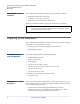
Quantum PX720 Unpacking and Installation Instructions Document 6444602-04 A01 March 2005 Table 1 Cluster Controller Ethernet Connections Tape Drive Cluster Cluster Controller Ethernet Connections Tape Drive Cluster 0 Eth1 - to internal network from the cabinet controller Eth2 - not used Eth3 - to first FC470 if present Eth4 - to tape drive cluster 1; Eth1 Tape Drive Cluster 1 Eth1 - to tape drive cluster 0; Eth4 Eth2 - not used Eth3 - to second FC470 if present Eth4 - to tape drive cluster 2; Eth1 T
Quantum PX720 Unpacking and Installation Instructions Document 6444602-04 A01 March 2005 Figure 24 Cluster Controller Ethernet Connections Cluster controller Tape drive cluster 0 I2 C Eth 1 Eth 2 Eth 3 Tape drive cluster 1 Eth 4 Tape drive cluster 2 Tape drive cluster 3 Tape drive cluster 4 Installing the Quantum PX720 Library 25
Quantum PX720 Unpacking and Installation Instructions Document 6444602-04 A01 March 2005 0 Cabling a SCSI PX720 Library To cable a SCSI Quantum PX720: 1 Open the back door of the Quantum PX720 to gain access to the tape drives and robotics controller (see figure 25).
Quantum PX720 Unpacking and Installation Instructions Document 6444602-04 A01 March 2005 3 Connect the host computers to the tape drives by routing SCSI cables up through the base of the library and along the right-hand side of the cabinet (see figure 26). Tech Tip: Start cabling with drive cluster 0 at the top of the library and work down.
Quantum PX720 Unpacking and Installation Instructions Document 6444602-04 A01 March 2005 Figure 27 Connecting the Library to the Local Area Network Ethernet port under service tray Local area Ethernet port Service port Cabinet controller enclosure shown outside for clarity 5 Close the back door. Cabling a Fibre Channel PX720 Library 0 Use the following procedure to connect the SCSI jumper cables, terminators, and Ethernet cables to the tape drive cluster(s) and FC470(s).
Quantum PX720 Unpacking and Installation Instructions Document 6444602-04 A01 March 2005 4 The SCSI, Ethernet, and Fibre Channel cables must be routed and stacked in the right-hand clamps correctly so the back door will close. Route the cables down through the cable channel on the right-hand side of the library. Refer to figure 29 and figure 30 for cable diagrams illustrating the correct cable placement.
Quantum PX720 Unpacking and Installation Instructions Document 6444602-04 A01 March 2005 30 Tape Drive Connection FC470 Connections/ Tape Drive Termination Tape drive 10, upper port Port 2 on third FC470 Tape drive 10, lower port Terminator Tape drive 11, upper port Port 3 on third FC470 Tape drive 11, lower port Terminator Tape drive 12, upper port Port 0 on fourth FC470 Tape drive 12, lower port Terminator Tape drive 13, upper port Port 1 on fourth FC470 Tape drive 13, lower port Termin
Quantum PX720 Unpacking and Installation Instructions Document 6444602-04 A01 March 2005 Figure 28 PX720 Interconnect (20 drives) FC470 1 SCSI 3 SCSI 2 SCSI 1 SCSI 0 Eth3 on drive cluster 0 Library SCSI HBA FC470 2 Tape drive 0 Tape drive 3 Tape drive 2 Tape drive 5 Tape drive 4 Tape drive 7 Tape drive 6 Tape drive 9 Tape drive 8 Tape drive 11 Tape drive 10 Tape drive 13 Tape drive 12 Tape drive 15 Tape drive 14 Tape drive 17 Tape drive 16 Tape drive cluster 4 Tape drive 19 Tape drive
Quantum PX720 Unpacking and Installation Instructions Document 6444602-04 A01 March 2005 Figure 29 Securing the SCSI, Ethernet, and Fibre Channel Cables SCSI (4 ports) Fibre Channel (2 ports) Ethernet (1 port) SCSI cables route Ethernet and Fibre Channel cables route Cable channel Excess SCSI cable 32 Installing the Quantum PX720 Library
Quantum PX720 Unpacking and Installation Instructions Document 6444602-04 A01 March 2005 Figure 30 FC470 Cable Connections Maximum Drive Configuration Installing the Quantum PX720 Library 33
Quantum PX720 Unpacking and Installation Instructions Document 6444602-04 A01 March 2005 Refer to the Quantum PX720 FC470 Upgrade Instructions (PN 6444614) for instructions on configuring the FC470 Fibre Channel bridge. Loading the Tape Cartridges 0 Initial Configuration 0 Before operating the library, load the appropriate tape cartridges (LTO or SDLT) into the library starting with the left-hand panels (refer to the Quantum PX720 User’s Guide PN 6444601 for more information on tape cartridges).
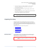
Quantum PX720 Unpacking and Installation Instructions Document 6444602-04 A01 March 2005 Figure 32 Menu Screen Select 3 From the Menu screen, use the up and down arrows to highlight Setup and press Select. 4 The library prompts you for your password (see figure 33). Figure 33 Password Screen 5 Enter the 6 digit password. The password is accepted after the sixth digit is entered. Note: The default password is 001122.
Quantum PX720 Unpacking and Installation Instructions Document 6444602-04 A01 March 2005 Figure 34 Setup Screen Back Select The Setup screen displays the following information: • IP Address (requires cabinet reboot) • IP Subnet Mask • IP Gateway • DHCP (default enabled) • Change Password • Restore Factory Settings • Drive Autoclean • Configured Drives • Configured Slots • Left Load Port (16) • Right Load Port (32) • Service Mode 6 To edit the setup information, use the up and dow
Quantum PX720 Unpacking and Installation Instructions Document 6444602-04 A01 March 2005 • To change the password, use the up and down arrows to select Change Password and press Select. To change the password, enter a 6-digit password using the numbers provided on the OCP. Press Select to accept the new password. When prompted, re-enter the password to confirm. • To enable autoclean, use the up and down arrows to select Autoclean and press Select.
Quantum PX720 Unpacking and Installation Instructions Document 6444602-04 A01 March 2005 38 Installing the Quantum PX720 Library