
User's Guide


Appendix B Installing the Slide Assembly in the Rack
Adjusting the Slide Assembly
104 ATL P1000 Series User’s Guide
Procedure (continued)
2
Move the slide assembly forward or backward as necessary.
3
When the slide assembly is in the desired position, tighten all outer
nuts:
a
Pull the slide assembly tray forward until you can access the
four rear screws.
b
Tighten each of the four rear nuts by holding the nut with an
11/32 inch open-ended wrench and then tightening its
corresponding screw with a Phillips screwdriver.
c
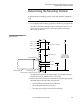
Extend the slide assembly out of the rack until both the
intermediate and inner channels of the slide rails lock (see
figure 57 on page 105).
The intermediate channels are secured by the intermediate
channel locks, which are located on the inner, back edge of the
intermediate channels.
d
Release the intermediate channel locks by rotating them
upward slightly.
Note:
Do not release the inner channel locks.
e
Push the slide assembly back into the rack until the access hole
on the inside of the intermediate channel exposes a screw.
f
Use a Phillips screwdriver to tighten the screw while holding
its corresponding nut with an 11/32 inch open-ended wrench.
g
Repeat steps 3e and 3f to tighten the remaining front nuts.
h
Press on the inner channel locks to release them.
The inner channel locks are located on the outer, back edge of
the inner channels.
i
Push the slide assembly tray back into the rack.
4
Check for clearance. If necessary, repeat this procedure to adjust
the slide assembly further.